Supercharge Your Innovation With Domain-Expert AI Agents!

Flow-actuated actuator and method

a technology of actuator and actuator body, applied in the direction of instruments, sealing/packing, borehole/well accessories, etc., can solve the problems that the diameter element reduction can limit other operations, and achieve the effect of more resistance to fluid flow

Inactive Publication Date: 2014-03-18
BAKER HUGHES INC
View PDF53 Cites 0 Cited by
  • Summary
  • Abstract
  • Description
  • Claims
  • Application Information

AI Technical Summary

Benefits of technology

This patent describes a new type of actuator that can move a separate member in response to fluid flow. It uses a tubular with a flow passageway and a movable member that can change the size of a flow area, creating a smaller area of flow when in a certain position. This results in a higher resistance to fluid flow, which causes the actuator to move the tubular with a force proportional to the fluid flow. This invention can be used in flow control devices, hydraulic systems, and other applications where precise actuation is needed.

Problems solved by technology

While these work well for their intended purpose, the reduced diameter elements can limit other operations simply due to diametrical patency.

Method used


Image

  • Flow-actuated actuator and method
  • Flow-actuated actuator and method
  • Flow-actuated actuator and method

Examples


Embodiment Construction

[0011]A detailed description of one or more embodiments of the disclosed apparatus and method are presented herein by way of exemplification and not limitation with reference to the Figures.

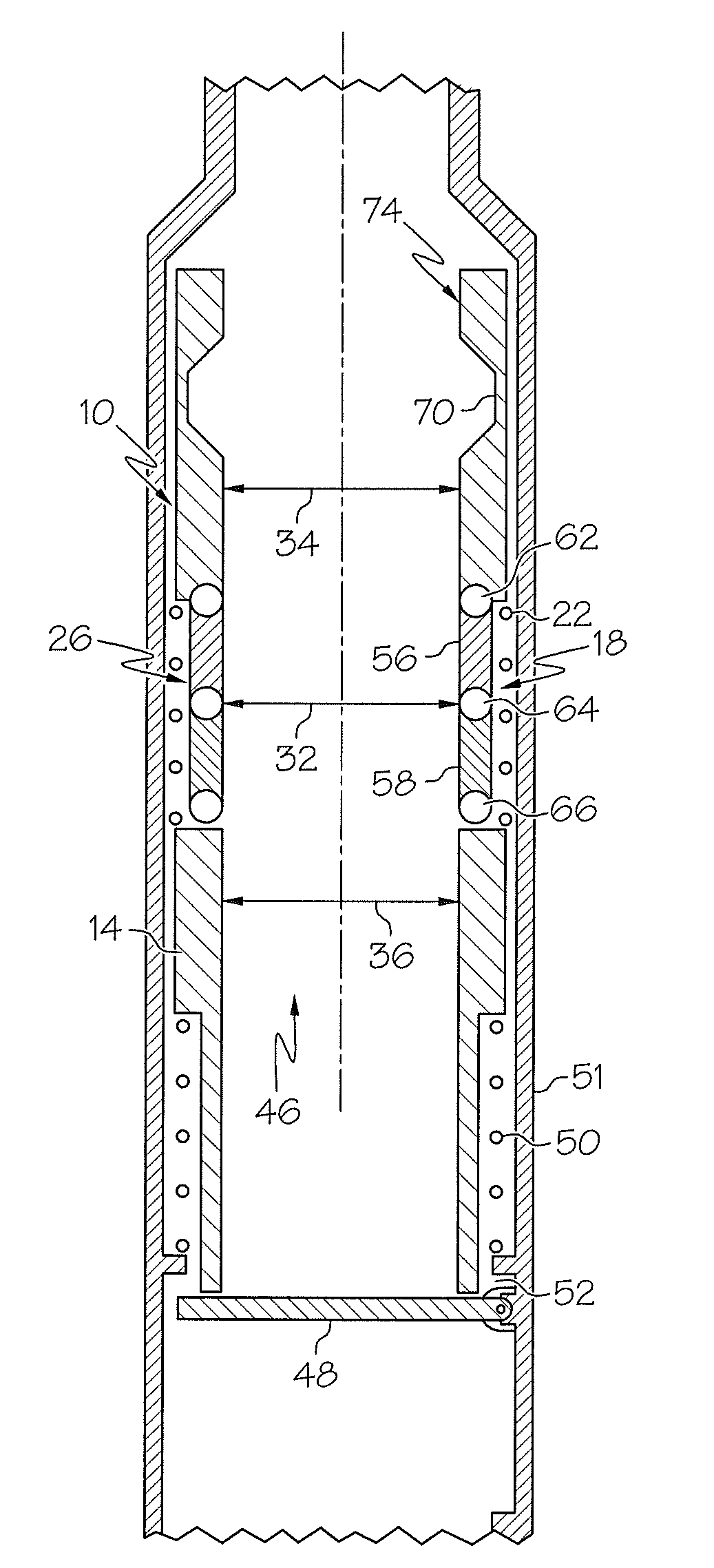
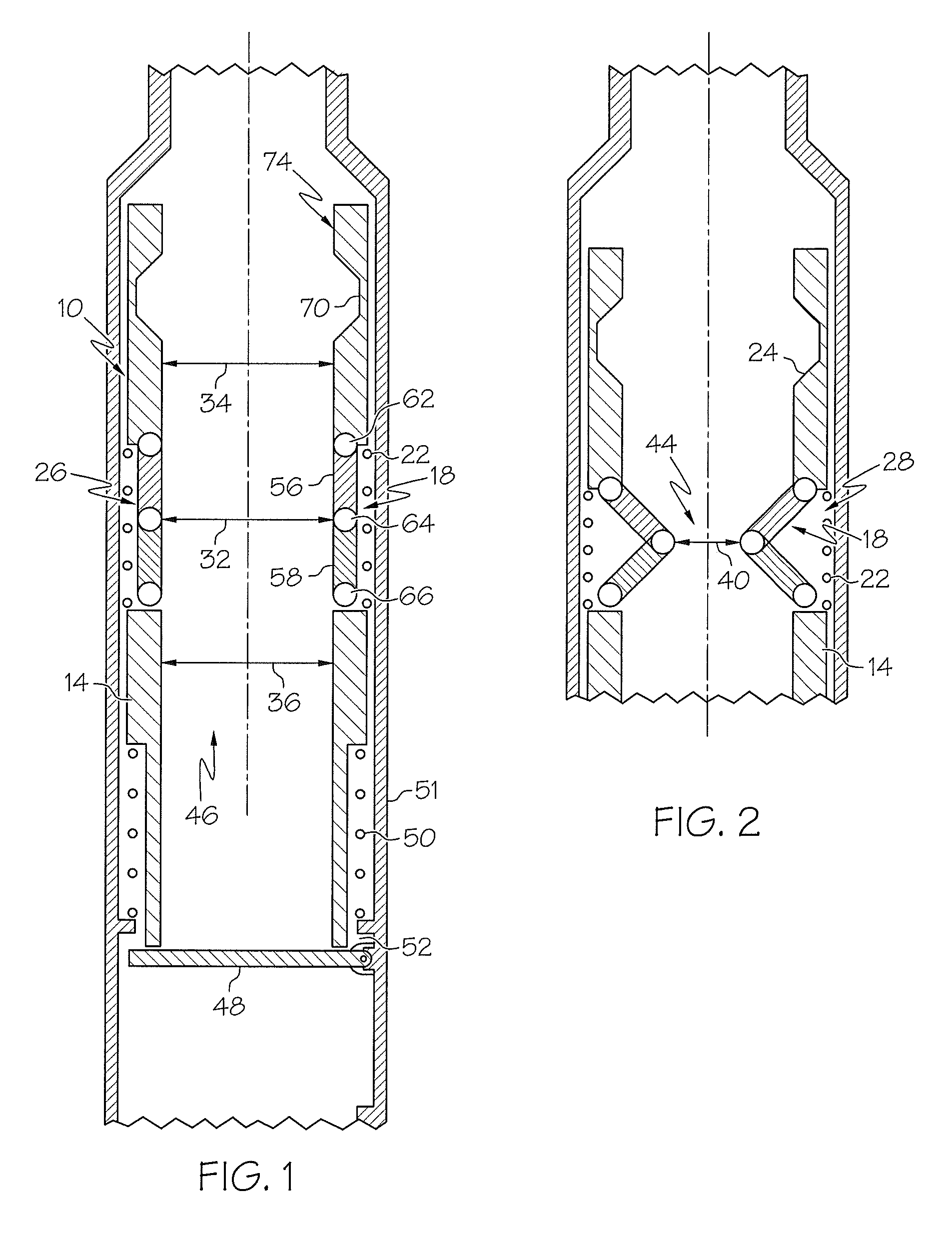
[0012]Referring to FIGS. 1 and 2, an embodiment of a flow-actuated actuator 10 is illustrated generally at 10. The actuator 10 is a full bore actuator that, when non-actuated does not present its own restriction to flow. Rather the actuator presents an unencumbered full bore. As such, the actuator 10 creates no obstruction to downhole intervention, for example, when in a non-actuating position yet provides a mechanism and method for actuating a downhole tool in response to fluid flow when in an actuating position. Although embodiments depicted herein are in reference to downhole applications, it should be noted that the flow-actuated actuators described herein are not limited to downhole applications, and as such can be used in any application needing a flow-actuated actuator.

[0013]The actuator 1...


PUM


Abstract

Disclosed herein is a flow-actuated actuator. The actuator includes, a tubular with a flow passageway having a first flow area, and at least one movable member in operable communication with the tubular. The at least one movable member is movable relative to the tubular between at least a first position and a second position, the at least one movable member configured to form a second flow area that is smaller than the first flow area when in the second position, the flow-actuated actuator is configured to move a separate member in response to fluid flow therethrough.

Description

BACKGROUND[0001]Downhole system operators are always receptive to new methods and devices to permit actuation of tools located downhole within a downhole system. Increasing flow rates of fluid pumped from surface can and has been harnessed as a method to permit actuation of a number of different types of devices in the downhole environment. In such methods downhole actuators typically use reduced diameter elements that resist fluid flow resulting in actuation forces that are proportional to the flow rate. While these work well for their intended purpose, the reduced diameter elements can limit other operations simply due to diametrical patency. Commonly then such actuators must be removed from the downhole system to allow full bore access. Devices and methods that permit actuation based on flow while not incurring the drawback noted would be well received in the art.BRIEF DESCRIPTION[0002]Disclosed herein is a flow-actuated actuator. The actuator includes, a tubular with a flow pass...

Claims


Application Information

Patent Timeline
Patent Type & Authority Patents(United States)
IPC IPC(8): F16K31/12
CPCE21B23/04E21B2034/005G05D7/0133E21B34/08Y10T137/7792Y10T137/7783Y10T137/7722Y10T137/7784Y10T137/0318E21B2200/05E21B34/14F15B15/14F15B15/24
Inventor PATTERSON, RICHARDLAKE, GARY B.XU, YANGBUSSEAR, TERRY R.
Owner BAKER HUGHES INC
Features
  • R&D
  • Intellectual Property
  • Life Sciences
  • Materials
  • Tech Scout
  • Unparalleled Data Quality
  • Higher Quality Content
  • 60% Fewer Hallucinations
Learn More