
Cabinet door with retractable panel

a technology of sliding doors and sliding doors, applied in the field of sliding doors, can solve the problems of significant injuries and the near zero of sliding doors, and achieve the effect of facilitating upward and/or inward directional movemen

Inactive Publication Date: 2014-04-01
MARESH JOSEPH D
View PDF8 Cites 3 Cited by
  • Summary
  • Abstract
  • Description
  • Claims
  • Application Information

AI Technical Summary

Benefits of technology

The patent describes a cabinet door assembly that can be opened and closed to access a chamber. The door has two parallel panels that can retract for safety. A stop member prevents the second panel from moving too far downward. The panels have ramp surfaces and a guide member that work together to move the second panel upward or inward in response to an impact force. This design allows for smooth and safe movement of the cabinet door.

Problems solved by technology

Serious injuries due to an impact with a cabinet door are well reported in the media, and typically are caused by a collision with a cabinet door and a person's head.
This hazardous event may be described with regards to conservation of momentum, where the product of the mass of two colliding objects and their respective velocities is conserved, and wherein m1v1=m2v2, however in the instance of the prior art, the velocity of the cabinet door may be near zero with no cabinet door reactive rotation due to the impact angle, thus causing a significant number of injuries each year.

Method used


Image

  • Cabinet door with retractable panel
  • Cabinet door with retractable panel
  • Cabinet door with retractable panel

Examples


first embodiment

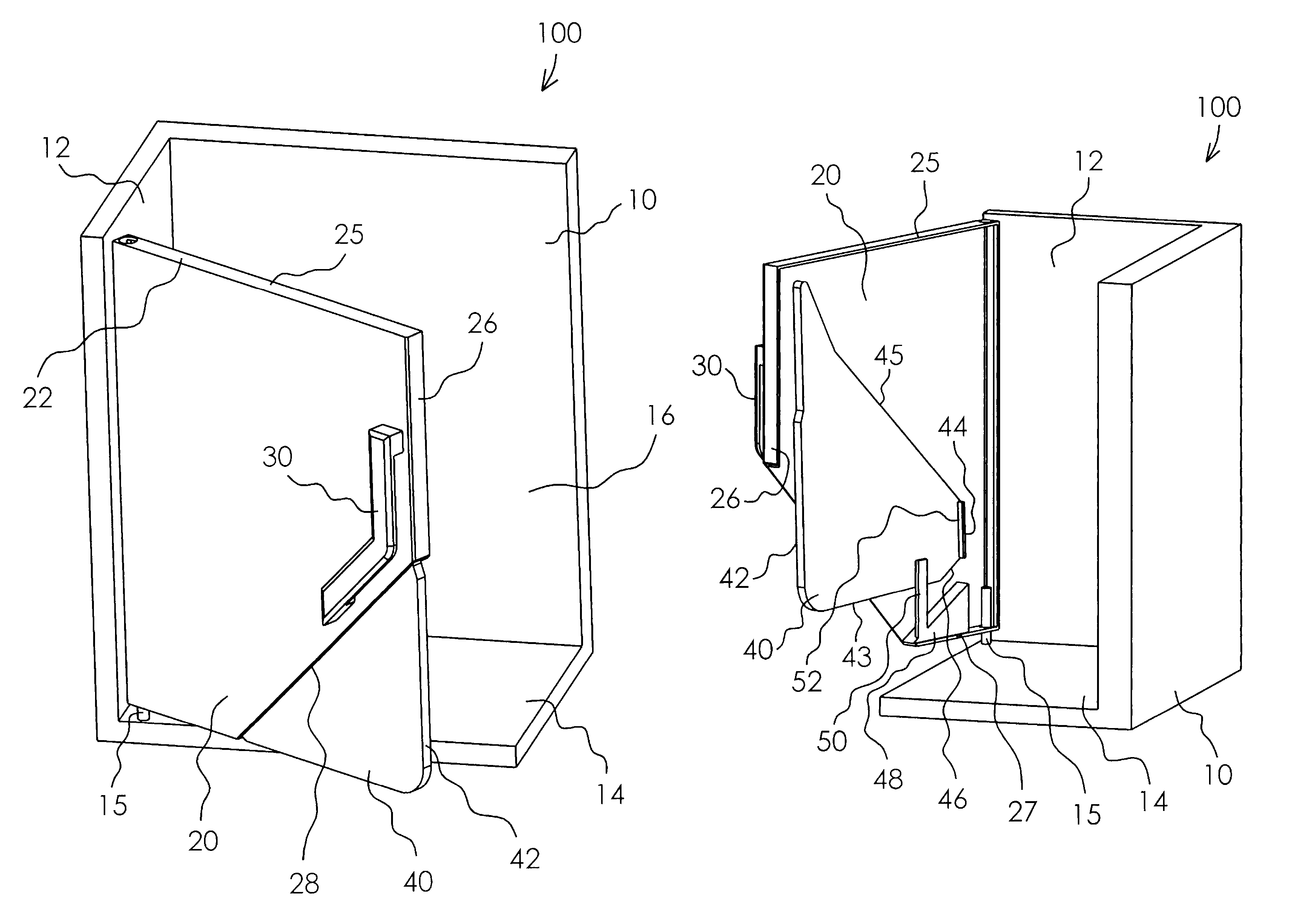
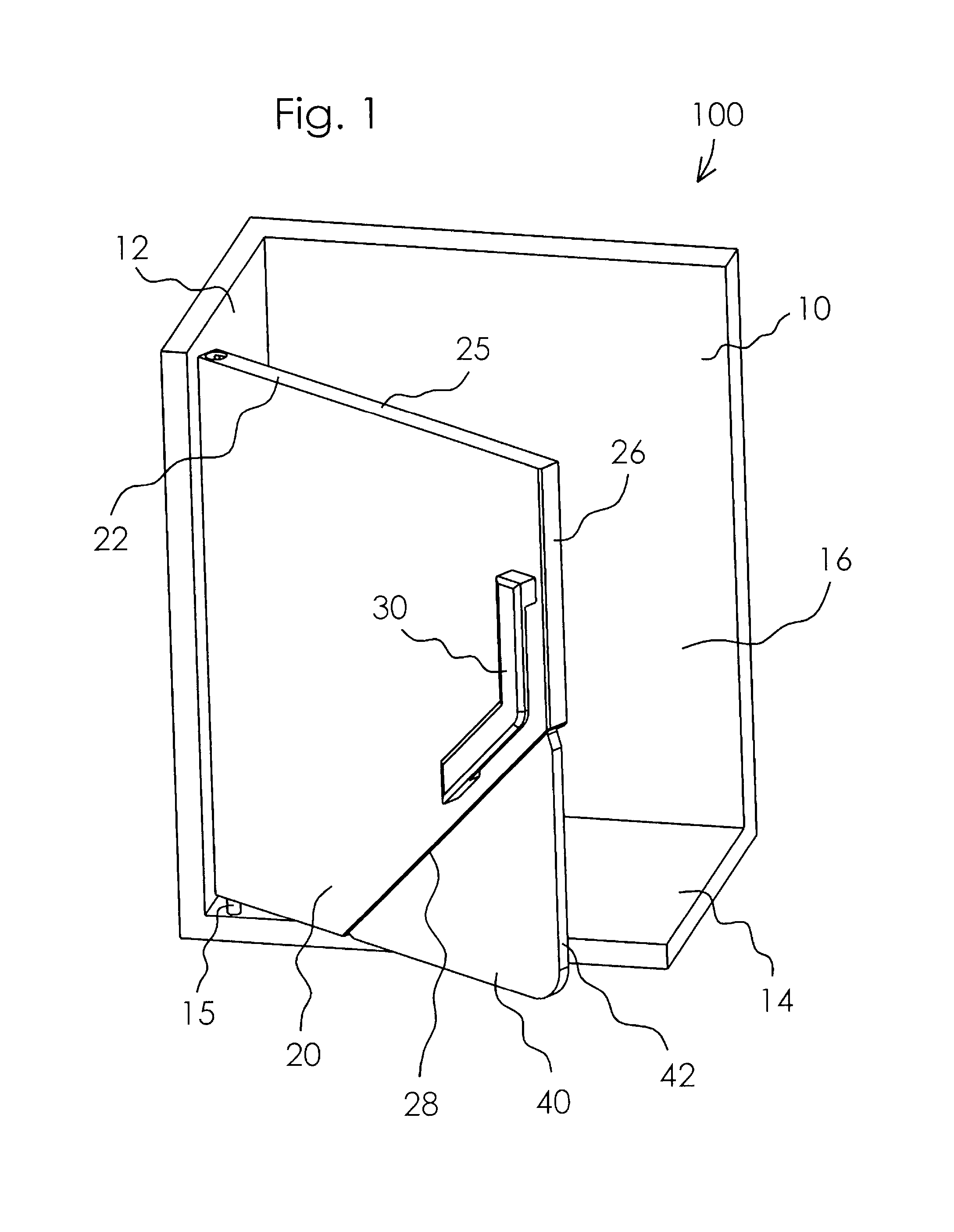
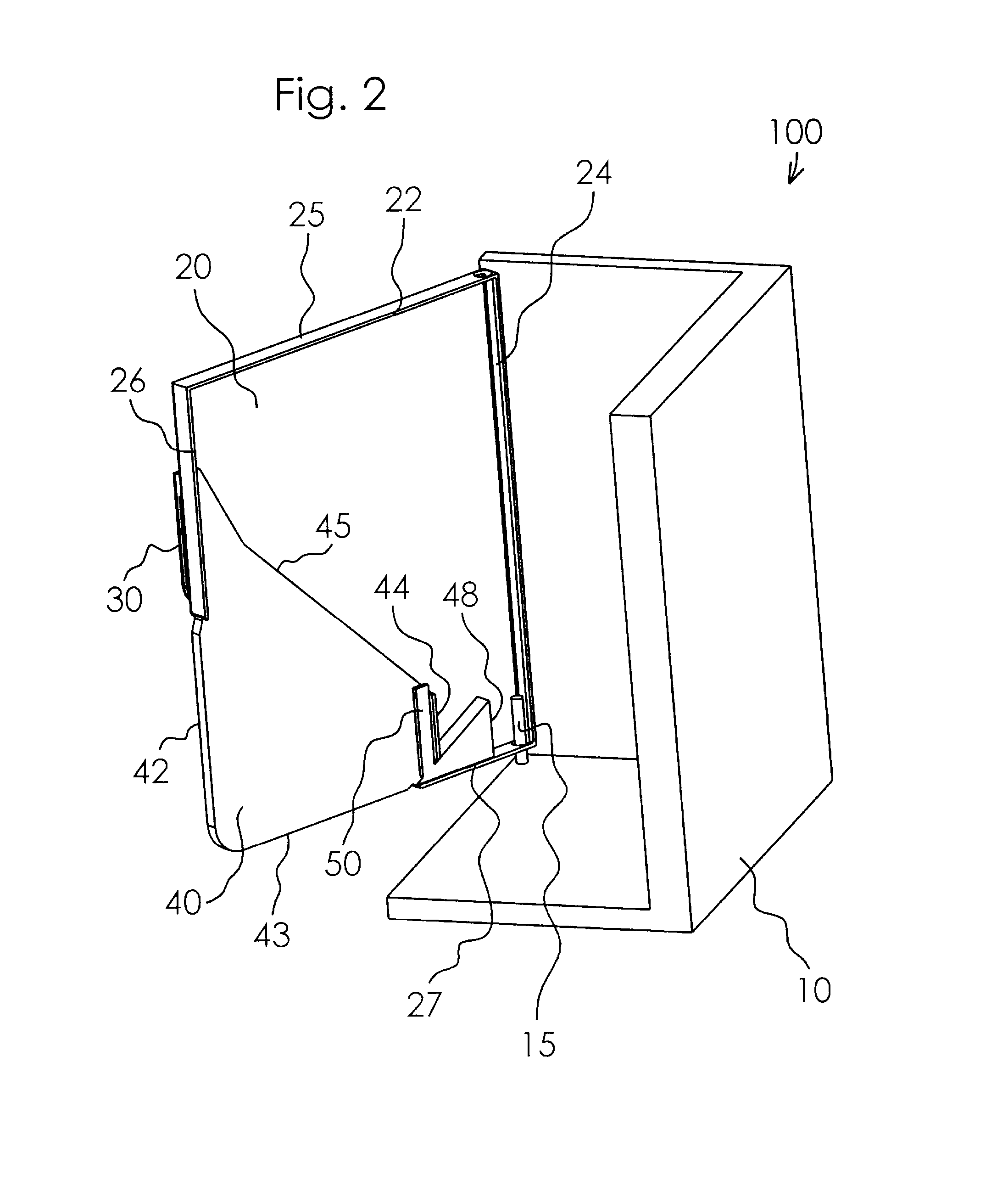
[0013]Referring first to FIG. 1, a cabinet, such as a kitchen cabinet, is generally identified by the reference numeral 100. The cabinet 100 is typically rigidly secured to a wall or the like at an elevated position to facilitate convenient access to the interior of the cabinet 100. The cabinet 100 comprises a back wall 10, sidewalls 12, a bottom 14 and a top wall or cover configured and rigidly secured together to define an interior chamber 16. For purposes of convenience in showing the interior structural components of the cabinet 100, the top wall and one of the sidewalls 12 are not shown in the drawings.

[0014]A door 20 forms the front of the cabinet 100. The door 20 may be substantially planar and include an upstanding flange 22 extending partially about the perimeter of the door 20. The flange 22 projects outward from and is oriented substantially perpendicular to the back or interior surface of the door 20. The door 20 is rotatably secured at the top and bottom of the cabinet ...

second embodiment

[0021]Referring now to FIG. 5, a cabinet door with a retractable panel is generally identified by the reference numeral 200. The cabinet 200 is substantially similar to the cabinet 100 described above with the exception that the cabinet 200 includes an extension spring 210 having one end 212 secured to the door panel 40 and an opposite end 214 secured to the ramp 48. The spring 210 is maintained in tension for returning the door panel 40 to the closed position after receipt of an impact force.

third embodiment

[0022]Referring now to FIG. 6, a cabinet door with a retractable panel is generally identified by the reference numeral 300. The cabinet 300 is substantially similar to the cabinet 100 described above with the exception that the cabinet 300 includes a magnet 310 secured to the stop member 52 and ferrous material 312 secured to the guide 50. The magnet 310 and ferrous material 312 cooperate to maintain the door panel 40 in the closed position.


PUM


Abstract

A cabinet door assembly is moveably mounted to a cabinet to selectively close a chamber. The cabinet door has a substantially planar first panel and a substantially planar second panel in a planar parallel configuration. The second panel may retract relative to the first panel upon application of an impact force to the second panel. A stop member may be incorporated to limit the downward movement of the second panel. Ramp surfaces and a guide member cooperate to facilitate upward and / or inward directional movement of the second panel relative to the first panel upon application of an impact force to the second panel.

Description

CROSS-REFERENCE TO RELATED APPLICATION[0001]This application claims the benefit of U.S. Provisional Application Ser. No. 61 / 463,204, filed Feb. 14, 2011, which application is incorporated herein by reference.BACKGROUND OF THE INVENTION[0002]The present invention relates to cabinet doors, and in particular to a safety feature integrated within a cabinet door for mitigating injuries due to head and / or body impact with a cabinet door.[0003]Serious injuries due to an impact with a cabinet door are well reported in the media, and typically are caused by a collision with a cabinet door and a person's head. In the most severe injuries, the cabinet door does not yield, or open or close during horizontal impact. In the instance of generally direct horizontal impact with the door edge, the impact force direction is directed toward the axis of rotation of the cabinet door, and thus the cabinet door will not rotate or move in reaction away from the impact force. In the instance of generally ver...

Claims


Application Information

Patent Timeline
Patent Type & Authority Patents(United States)
IPC IPC(8): E06B3/00
CPCE06B7/28E06B5/006E06B3/92E06B3/00
Inventor MARESH, JOSEPH, D
Owner MARESH JOSEPH D
Learn More