Pneumatic control system for aerodynamic surfaces

a control system and aerodynamic technology, applied in the field of flight control systems, can solve the problems of affecting the overall utility of the aircraft, affecting the flight safety of the aircraft, so as to facilitate the upward and downward actuation of the control surface, facilitate the inflation and deflation of the cells, and minimize the effect of pillowing

Active Publication Date: 2009-09-10
THE BOEING CO
View PDF6 Cites 27 Cited by
  • Summary
  • Abstract
  • Description
  • Claims
  • Application Information

AI Technical Summary

Benefits of technology

[0015]The flight control system comprises at least one control surface, a chamber connecting the control surface to the airfoil, and a pneumatic mechanism for actuating the chamber. The chamber may be formed with one and, more preferably, a pair of cells that may be separated from one another by at least one membrane that is preferably of constant length.
[0016]The pneumatic mechanism is fluidly connected to the cells and is configured to effectuate or cause a volume change or differential in the cells in order to actuate or move the control surface. Such volume differential occurs as a result of the pressurization / inflation of one cell and / or the de-pressurization / deflation of the remaining cell in order to deflect the control surface upwardly or downwardly. In this manner, the pneumatic mechanism is configured to dynamically inflate and / or deflate the pair of cells in order to differentially add and subtract length from stretchable outer surfaces that define the cells.
[0017]The membrane may preferably comprise a unitary structure or layer. However, the membrane may be provided in alternative constructions, shapes, sizes and configurations including, but not limited to, multi-layer arrangements or arrangements comprising multiple components. In addition, the chamber may be configured such that the cells are disposed in either contacting or non-contacting relation to one another. The membrane may be configured to remain at a substantially constant length between the airfoil (e.g., wing) and the control surface and is preferably configured to be non-stretchable. The membrane may be flexible in order to facilitate upward and downward actuation of the control surface during inflation and deflation of the cells.
[0018]The cells may be stacked atop one another although other arrangements are contemplated. The outer surfaces of the cells may be arranged so as to provide a continuation of the curvature of mold lines that define the airfoil and, in this regard, the outer surfaces of the cells are preferably substantially flush with the mold lines and with the control surface. The outer surfaces of the cells are preferably fabricated of stretchable material in order to facilitate inflation and deflation of the cells while minimizing pillowing.
[0019]The control surface may be configured as a trailing edge device or a leading edge device and may further be provided in a fixed or rigid configuration (e.g., a composite solid), a semi-rigid configuration (e.g., flexible foam) or in an inflatable configuration or any combination thereof. The control surface and airfoil may be provided in a wide variety of alternative configurations including, but not limited to, a flap or elevon mounted on the trailing edge. The control surface may also be configured to be mounted on a leading edge in a variety of configurations including, but not limited to, flaps, spoilers, spliterons, drooping leading edge devices and other configurations. The airfoil may be provided in a variety of configurations including, but not limited to, a wing, tail surface or tail section, vertical stabilizer, horizontal stabilizer, stabiliator, elevator, ruddervator, and flaperon.
[0020]In one embodiment, the pneumatic mechanism may be configured as a free air piston having a pair of conduits extending from opposing sides of the free air piston to ports on the cells. The conduit material is preferably radar transparent or a low visibility material such as vinyl tubing or other suitable material that facilitates deployment of the wings during inflation. The pneumatic mechanism may include a fill system to account for pressure differential that may occur with changes in the ambient pressure as may occur with altitude changes. The fill system may comprise a pressurized gas source such as a pressure bottle or an on-board compressor or gas generator.

Problems solved by technology

However, while the wing structure may be radar transparent, current mechanisms for actuating the control surfaces of the wings such as ailerons, flaps and leading edge devices require the use of mechanisms and / or materials that may not be radar transparent.
Even if such current mechanisms are inherently radar transparent, they may possess certain drawbacks and deficiencies that detract from their overall utility.
However, because most aircraft require some type of mechanism for controlling the aircraft flight attitude, it is necessary to relocate the control mechanism to the propulsion system.
Unfortunately, arranging the propulsion system to provide the aircraft with directional flight control capability may necessitate the use of independently controllable throttles on at least two separate propulsion units.
Although such propulsion systems are available, they are also necessarily complex, costly, bulky and heavy.
A further drawback associated with the use of the propulsion system as the source of directional control is that a loss of power in the propulsion system not only results in a loss of propulsive force to the aircraft, but also a loss in directional control of the aircraft.
Unfortunately, because most electromechanical actuators are constructed of metallic materials, they typically exhibit high radar reflectivity.
Unfortunately, the piezoelectric strips operate via dielectric (i.e., voltage) potential which is the very mechanism by which radar sees a surface and therefore rendering such piezoelectric strips unsuitable for use in aircraft requiring radar transparency.
Unfortunately, the use of wing warping on certain aircraft may result in certain disadvantages such as aerodynamic drag due to exposed cables.
Although modern cables are available in radar transparent materials, the exposed cables impose a significant aerodynamic drag penalty which increases with the increasing speed of the aircraft.

Method used


Image

  • Pneumatic control system for aerodynamic surfaces
  • Pneumatic control system for aerodynamic surfaces
  • Pneumatic control system for aerodynamic surfaces

Examples


Embodiment Construction

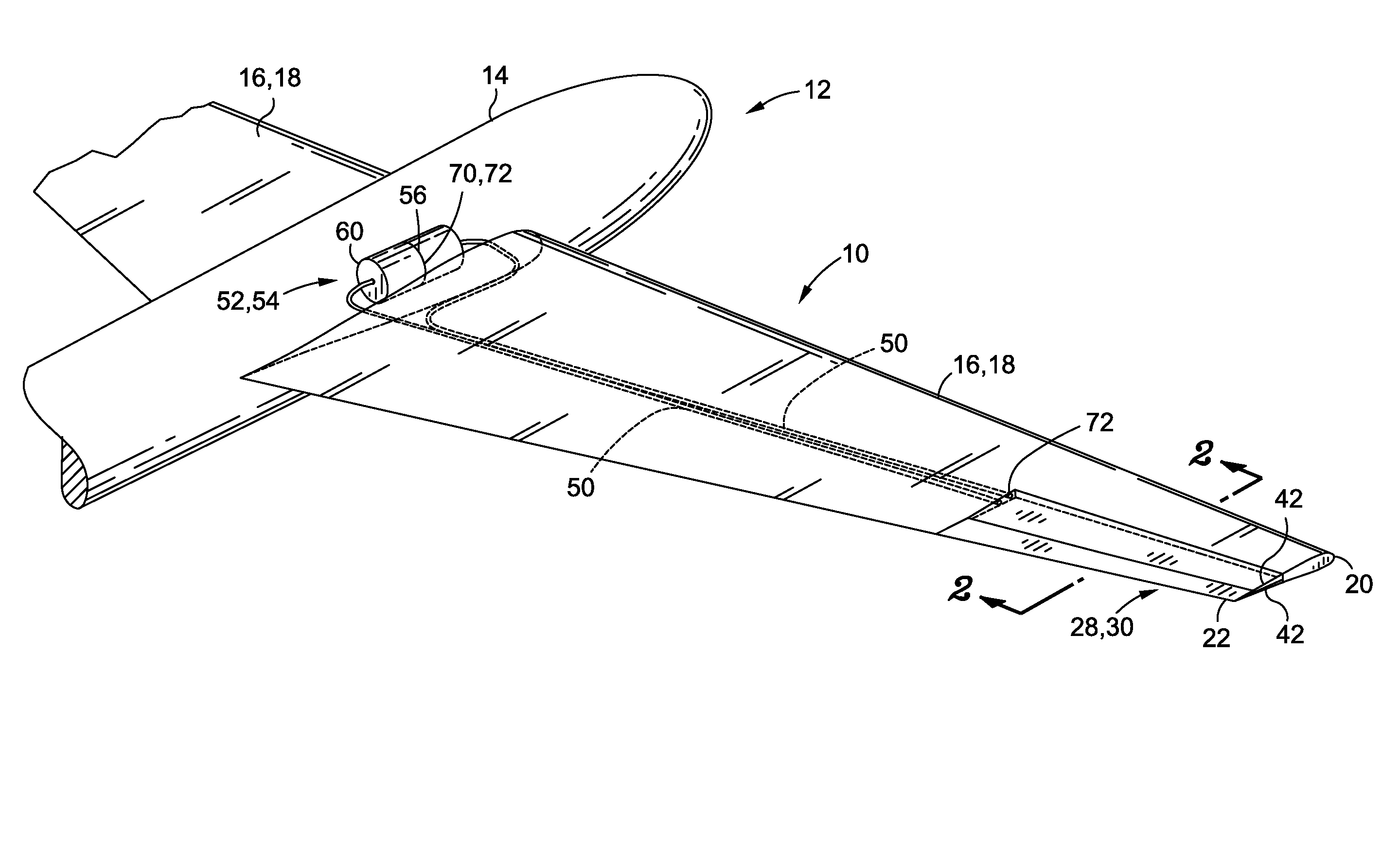
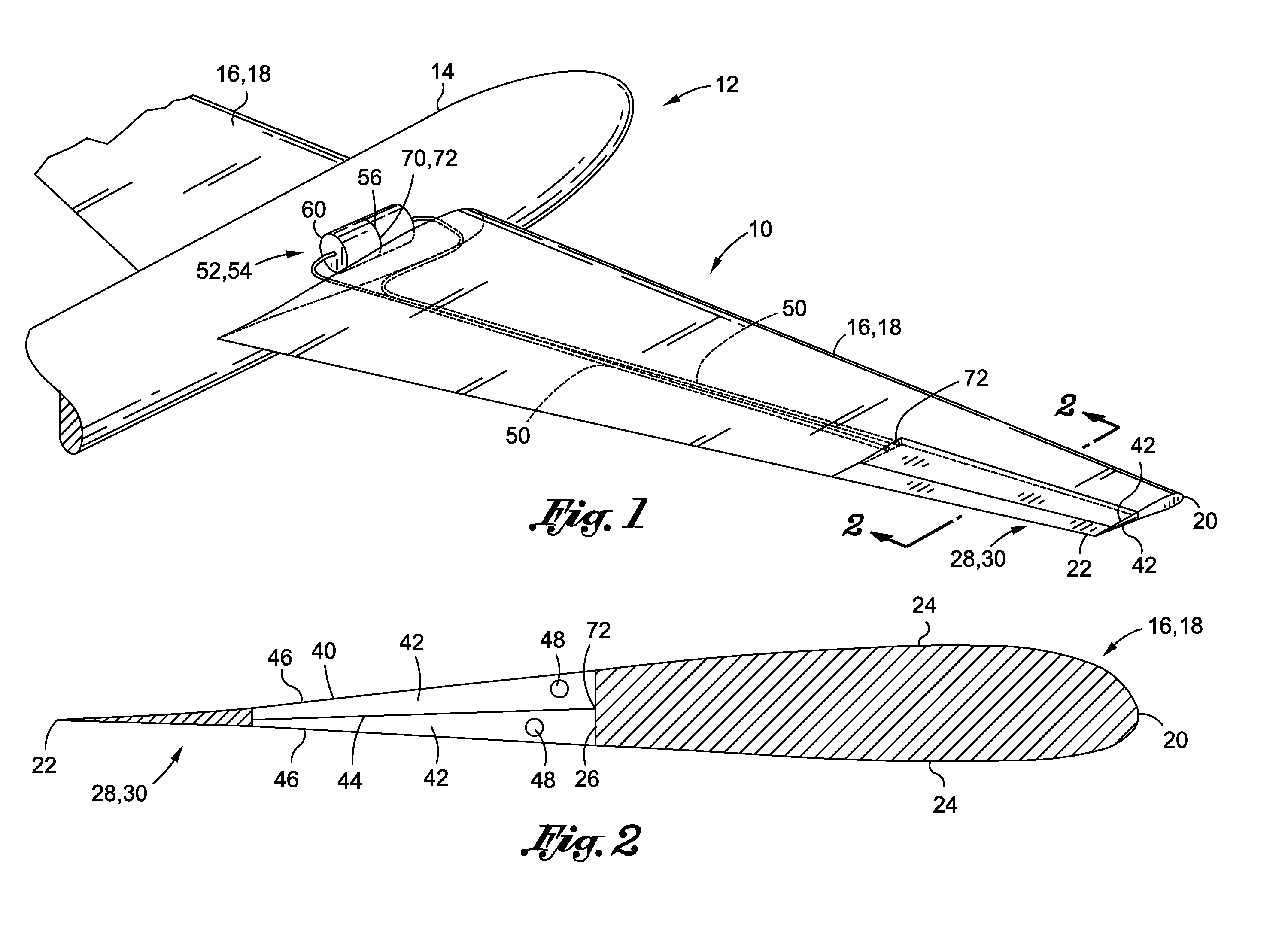
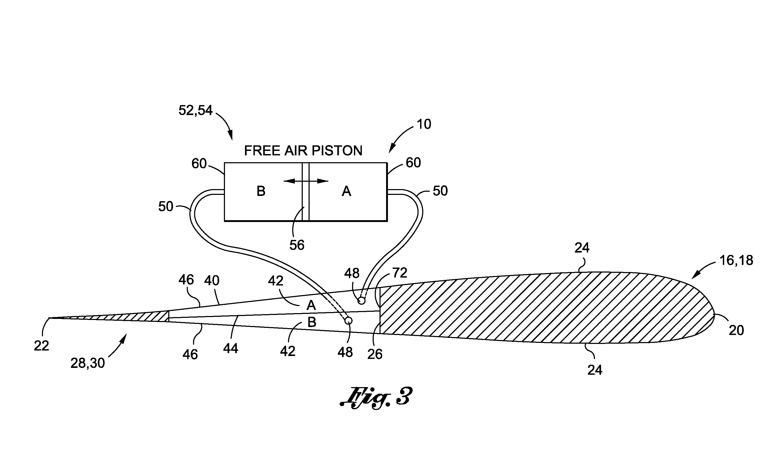
[0039]Referring now to the drawings wherein the showings are for purposes of illustrating preferred and various embodiments of the invention only and not for purposes of limiting the same, FIG. 1 is an illustration of an aircraft 12 having one embodiment of a pneumatic control system 10 for a flight control surface 28 mounted on an airfoil 16 such as an aircraft wing 18. In FIG. 1, the control surface 28 is shown configured as an aileron 30 mounted adjacent to a trailing edge 22 of the wing 18. However the control surface 28 and airfoil 16 to which it is attached may be provided in a wide variety of alternative configurations.

[0040]For example, the control surface 28 may be configured as a flap 34 or elevon mounted on the trailing edge 22. In another embodiment, the control surface 28 may be configured to be mounted on a leading edge 20 of the wing 18 in a variety of configurations including, but not limited to, flaps, spoilers, drooping leading edge devices and various alternative ...


PUM


Abstract

A flight control system for an airfoil comprises a control surface, a chamber connecting the control surface to the airfoil, and a pneumatic mechanism fluidly connected to the chamber. The chamber may be comprised of at least two cells that may be fluidly separated by a membrane. The pneumatic mechanism is configured to provide differential pressure to the cells in order to alternately increase volume/pressure of the cells to cause deflection of the control surface. The cells may have a stretchable outer surface to allow for changes in the length of the outer surface in response to inflation/deflation of the cells. The outer surface of the cells may be substantially continuous with outer mold lines of the airfoil and of the control surface.

Description

CROSS-REFERENCE TO RELATED APPLICATIONS[0001](Not Applicable)STATEMENT RE: FEDERALLY SPONSORED RESEARCH / DEVELOPMENT[0002](Not Applicable)FIELD[0003]The present invention relates generally to aircraft control surfaces and, more particularly, to a flight control system for pneumatically actuating a control surface of an aircraft or other vehicle.BACKGROUND[0004]High altitude and long endurance aircraft such as certain unmanned air vehicles (UAV's) may require wings having a long span and a high aspect ratio. Such UAV's may be configured to operate in a loitering capacity at relatively high altitudes (e.g., 50,000 to 80,000 feet) for prolonged periods of time to provide coverage of a specific geographic area. The coverage may include intelligence gathering, surveillance and reconnaissance operations wherein information may be gathered by the UAV and transmitted to ground units or other air units.[0005]Although UAV's may be ground-launched from a runway in the conventional manner for ai...

Claims


Application Information

Patent Timeline
Patent Type & Authority Applications(United States)
IPC IPC(8): B64C3/30B64C3/44
CPCB64C3/46B64C3/30
Inventor LUTKE, KEVIN R.KUTZMANN, AARON J.
Owner THE BOEING CO
Why Eureka
Try Eureka