Enclosure with duct mounted electronic components

a technology of electronic components and enclosures, applied in the direction of cooling/ventilation/heating modifications, cabinets, standard racks/cabinets, etc., can solve the problem of high operating temperatur

Inactive Publication Date: 2014-04-01
GENERAL ELECTRIC CO
View PDF20 Cites 18 Cited by
  • Summary
  • Abstract
  • Description
  • Claims
  • Application Information

AI Technical Summary

Problems solved by technology

Such densely packed electrical components may result in relatively high operating temperatures.
Moreover, industrial control system customers generally intend to place such control systems in locations where ambient temperatures may be high and environmental contaminants such as dust, salt, debris, and the like may be common.
There is thus somewhat of a tradeoff in operational parameters when selecting an enclosure for a particular purpose and location.

Method used


Image

  • Enclosure with duct mounted electronic components
  • Enclosure with duct mounted electronic components
  • Enclosure with duct mounted electronic components

Examples


Embodiment Construction

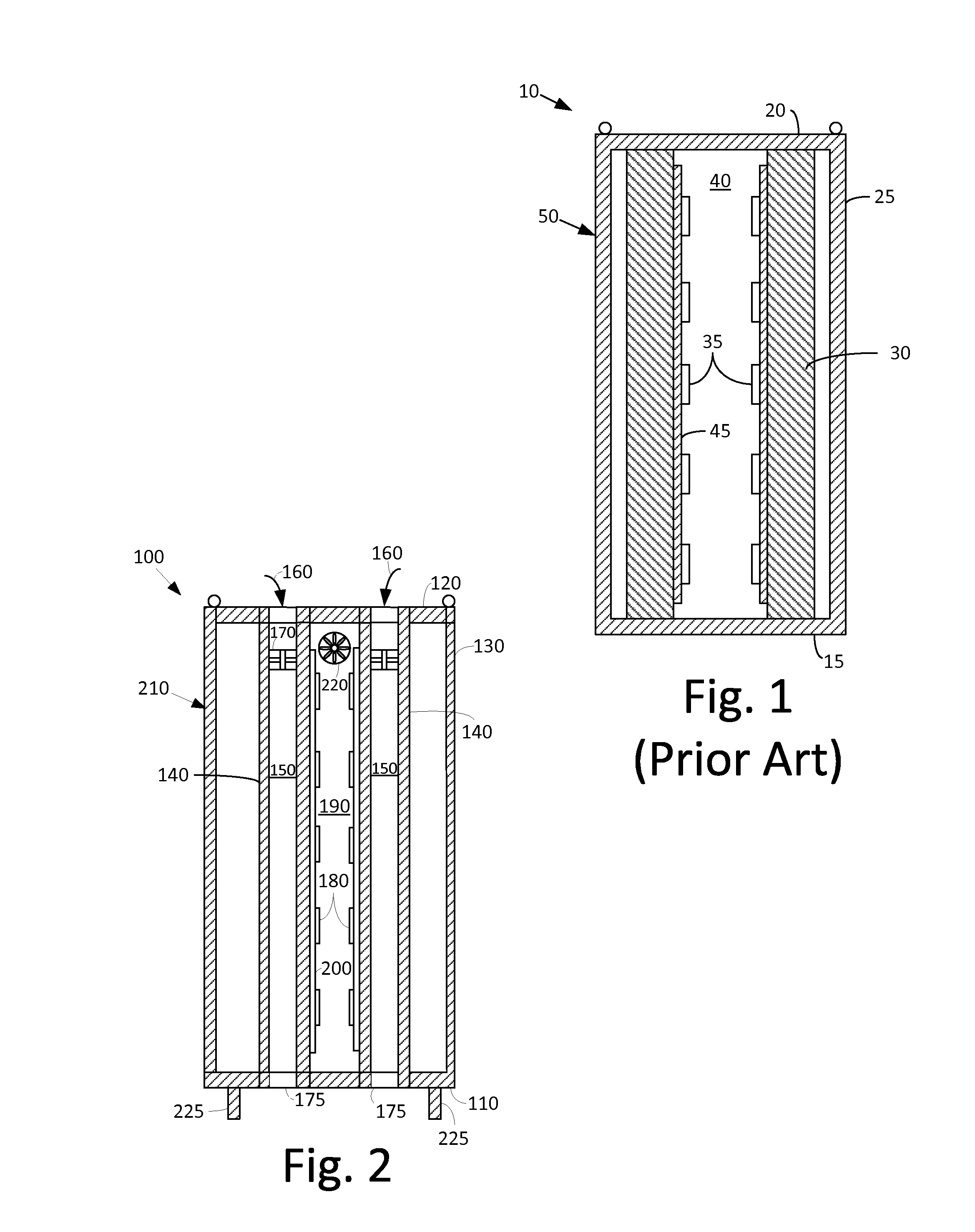
[0015]Referring now to the drawings, in which like numerals refer to like elements throughout the several views, FIG. 1 shows a side cross-sectional view of a known enclosure 10. Generally described, the enclosure includes a base 15, a roof 20, and a number of sidewall 25. The overall enclosure 10 may be of any size, shape, or configuration. The base 15, the roof 20, and the sidewall 25 may be made out of a sheet metal or other types of substantially rigid materials intended for use in relatively hostile conditions.

[0016]The enclosure 10 may include a number of internal support beams 30 positioned therein. The support beams 30 may have any size, shape, or configuration. The support beams 30 may extend from the base 15 to the roof 20. The support beams 30 may be made out of steel or other types of substantially rigid materials. Any number of the support beams 30 may be used.

[0017]A number of electrical components 35 may be positioned in an interior 40 of the enclosure 10. Specificall...


PUM


Abstract

The present application provides for an enclosure for mounting electrical components therein. The enclosure may include a base, a roof, a number of side walls, and one or more support ducts extending from the base to the roof. The supports ducts may include an air channel therein extending from the base to the roof.

Description

TECHNICAL FIELD[0001]The present application and the resultant patent relate generally to enclosures for use with electrical components and more particularly relate to a sealed enclosure with duct mounted electrical components therein and with a cooling flow through the duct.BACKGROUND OF THE INVENTION[0002]Electronic control systems such as power plant control systems and the like generally are densely packed within an enclosure. Such densely packed electrical components may result in relatively high operating temperatures. These high operating temperatures and other thermal considerations may have a bearing on the minimum form factor to which the control systems may be designed, the maximum operating speeds, and the overall performance of the control systems.[0003]Moreover, industrial control system customers generally intend to place such control systems in locations where ambient temperatures may be high and environmental contaminants such as dust, salt, debris, and the like may...

Claims


Application Information

Patent Timeline
Patent Type & Authority Patents(United States)
IPC IPC(8): H05K7/20
CPCH05K7/20127H05K7/20163H05K7/206
Inventor MOORE, CHRISTOPHER, TODD
Owner GENERAL ELECTRIC CO
Why Eureka
Try Eureka