Locking clip and system

a technology of locking clip and clip, which is applied in the field of locking clip, can solve the problems of difficult reliance on visual verification as to the condition of the clip

Inactive Publication Date: 2014-04-15
DELLE DONNE DEAN
View PDF49 Cites 12 Cited by
  • Summary
  • Abstract
  • Description
  • Claims
  • Application Information

AI Technical Summary

Problems solved by technology

However, a need still exists for a locking clip capable of an easy and efficient transition between an open condition and a closed condition without requiring a wire-to-wire engagement, or significant deformation of the wire, since corrosion and / or change in resiliency, e.g., increased rigidity, of the wire may interfere with the operation of the clip.
As can be appreciated, the relatively rapidity with which hooks and lures are changed, and the relatively small size of locking clips makes reliance on visual verification as to the condition of the clip difficult.

Method used


Image

  • Locking clip and system
  • Locking clip and system
  • Locking clip and system

Examples


Embodiment Construction

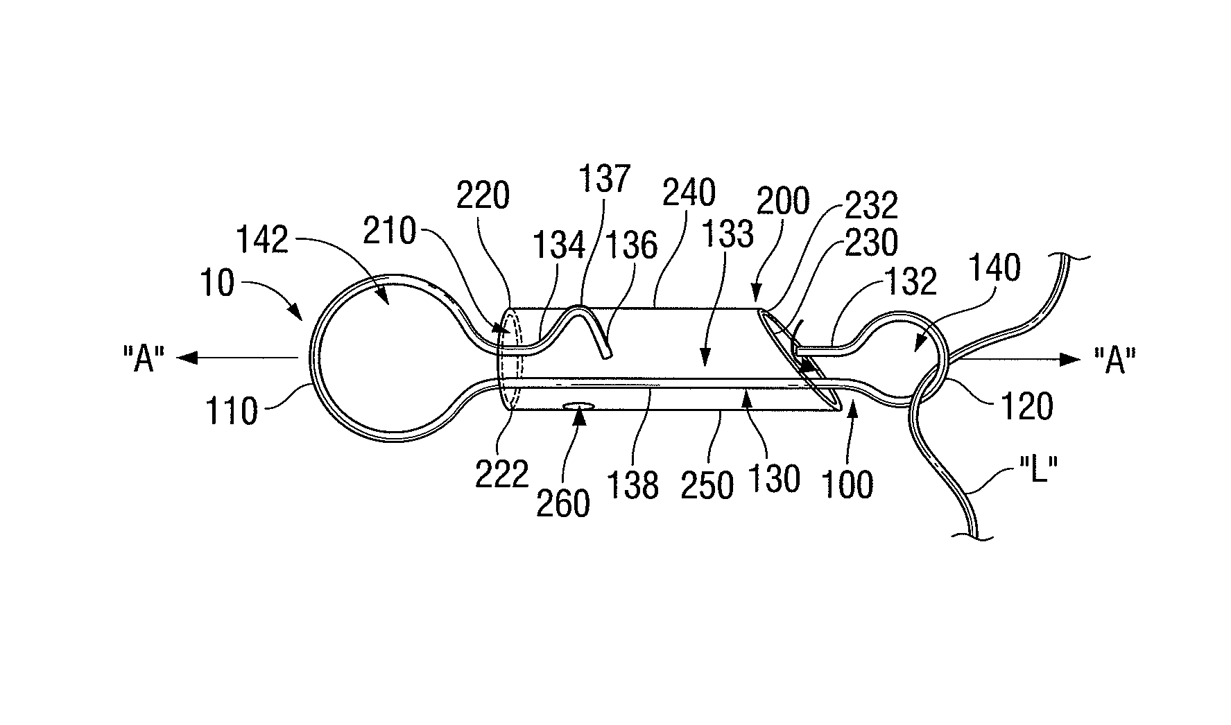
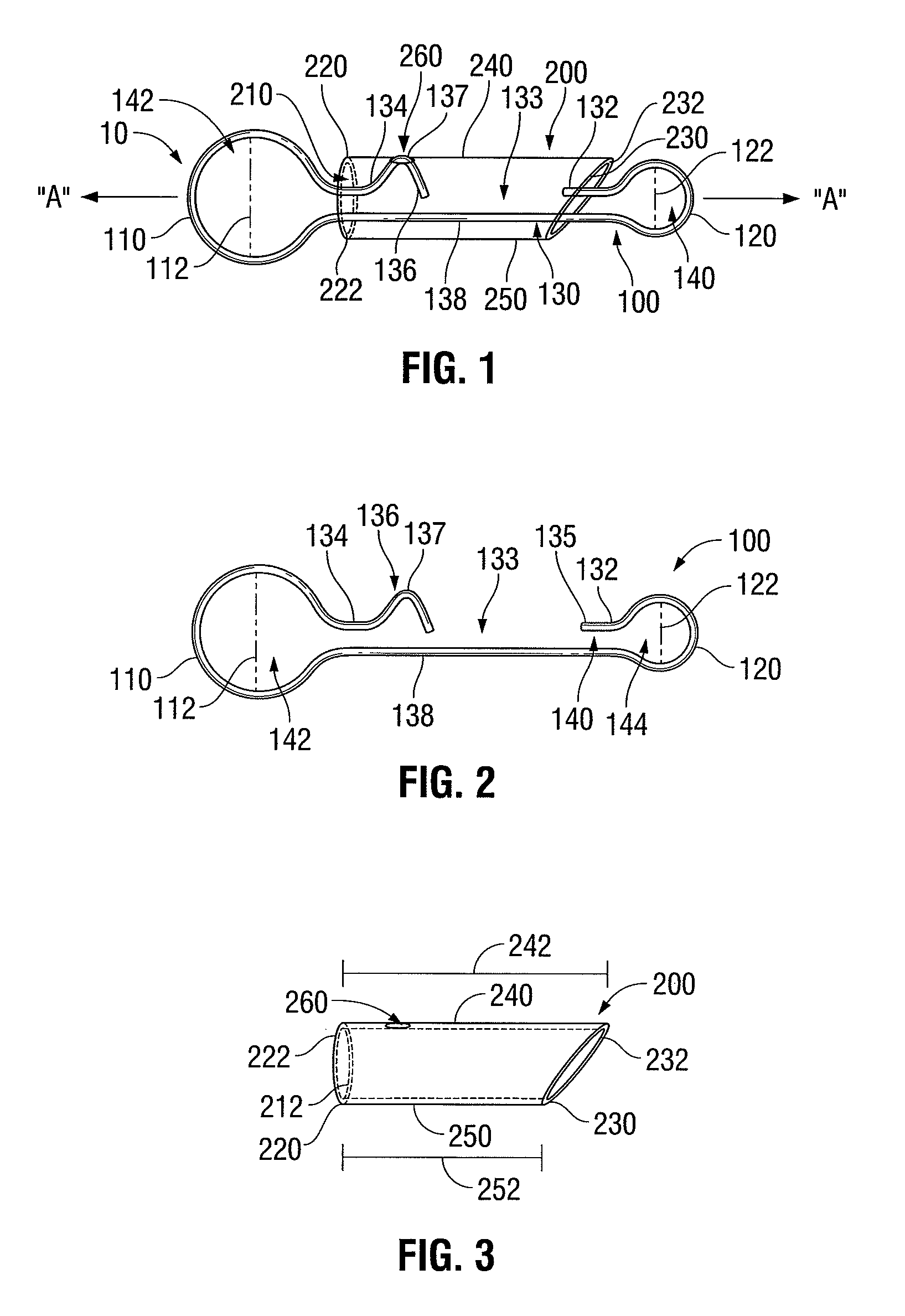
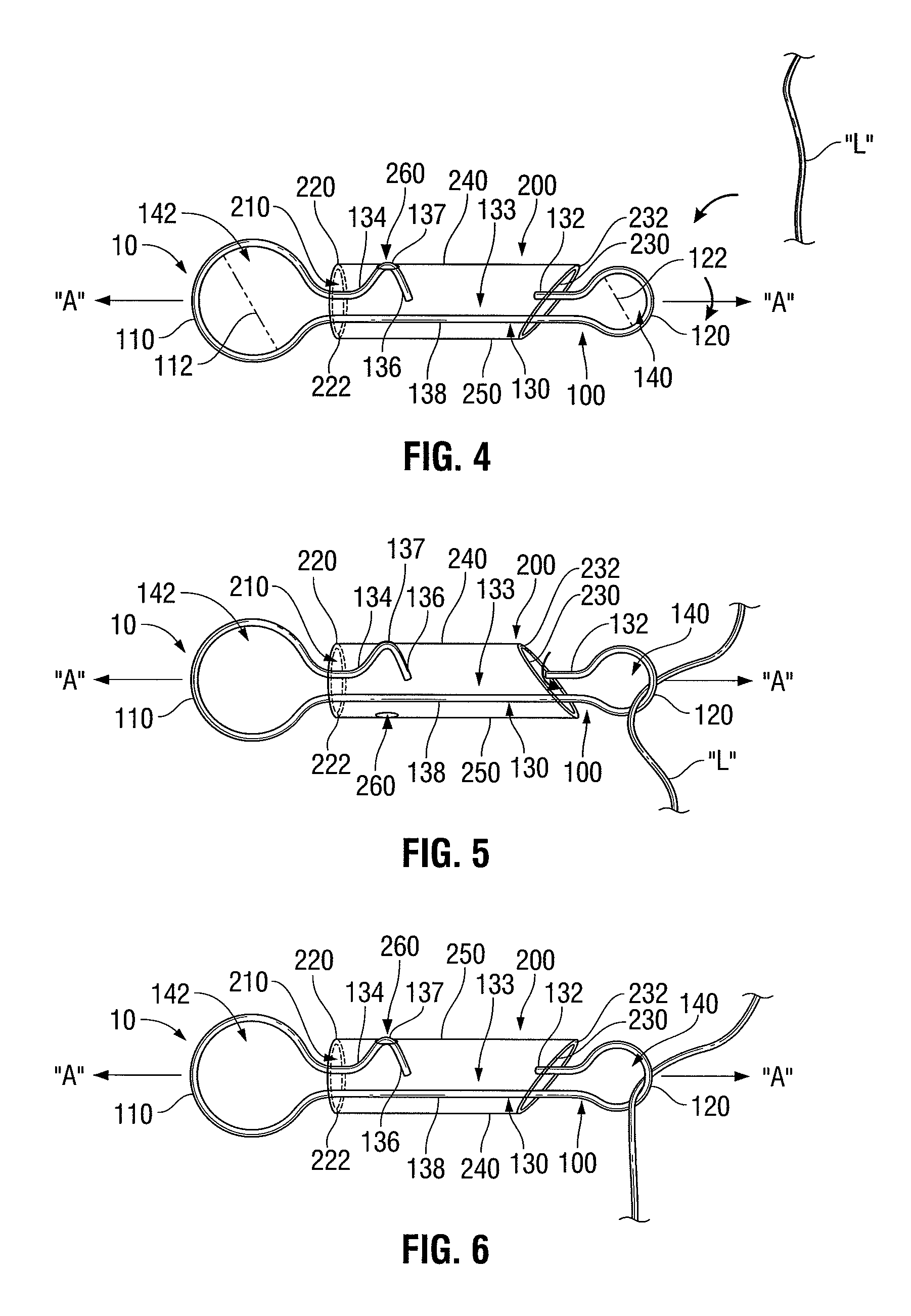
[0030]Turning now to FIG. 1, one illustrative embodiment of a locking clip provided in accordance with the present disclosure is shown generally identified by reference numeral 10. Locking clip 10 includes a loop portion 100 and a sleeve 200 disposed about loop portion 100. As will be described in greater detail below, sleeve 200 is rotatable about longitudinal axis “A-A” and relative to loop portion 100 between an open position (FIG. 5) and a closed position (FIGS. 4 and 6). In the open position, an object, e.g., a fishing line “L” (see FIGS. 4-6), may be inserted into and / or removed from loop portion 100, while, in the closed, or locked position, the fishing line “L” (FIGS. 4-6) is retained in engagement with loop portion 100.

[0031]Loop portion 100, as best shown in FIG. 2, may be formed from metal wire stock, or any other suitable material, e.g., a non-corrosive metal, and generally includes a first end 110, a second end 120, and an intermediate section 130 interconnecting the fi...


PUM


Abstract

A locking clip for securing one or more objects thereon includes a loop portion and a sleeve. The loop portion defines first and second ends interconnected by first and second intermediate segments. The first intermediate segment includes a gap defined therein. The sleeve is disposed about the first and second intermediate segments between the first and second ends of the loop portion. The sleeve is rotatable relative to the loop portion between a closed position, wherein the sleeve extends completely along a length of the gap to inhibit passage of the object(s) therethrough, and an open position, wherein the sleeve extends only partially along the length of the gap to permit passage of the object(s) therethrough. The loop portion and / or the sleeve also includes a feedback feature configured to produce an audible and / or a tactile feedback response when the sleeve is rotated to the closed and / or the open position.

Description

BACKGROUND[0001]1. Technical Field[0002]The present disclosure relates to a locking clip. More particularly, the present disclosure relates to locking clips that provide audible and / or tactile feedback to the user upon transitioning of the clip between an open condition and a closed condition as well as systems for use therewith.[0003]2. Description of Related Art[0004]Clips are commonly used, for example, to releasably secure fishing hooks, weights, or lures to a fishing line, obviating the need to cut and re-tie the line each time it is desired to change the hook or lure. A typical clip for attaching a fishing line to a hook or lure includes a wire loop that is capable of transitioning between an open condition, for positioning of the hook or lure about the clip, e.g., for inserting an open end of the clip through an aperture define through the hook or lure, and a closed condition, for securing the hook or lure to the clip, e.g., for inhibiting disengagement of the hook or lure fr...

Claims


Application Information

Patent Timeline
Patent Type & Authority Patents(United States)
IPC IPC(8): F16G15/04F16G15/00A01K91/03
CPCA01K93/02A01K91/04Y10T24/45382Y10T24/44017Y10T24/45089
Inventor DELLE, DONNE, DEAN
Owner DELLE DONNE DEAN
Why Eureka
Try Eureka