
Renewable energy powered light assembly

a technology of renewable energy and light assembly, which is applied in the field of light assembly, can solve the problems of poor air quality and global warming, volatile electricity price, and harmful use of certain fuels, and achieve the effects of reducing the cost of electricity consumption, and improving the quality of li

Active Publication Date: 2014-04-15
CUMBERLAND HOLLY S
View PDF17 Cites 2 Cited by
  • Summary
  • Abstract
  • Description
  • Claims
  • Application Information

AI Technical Summary

Benefits of technology

The solution provides a cost-effective and environmentally friendly lighting solution that can be easily installed and operated, offering a low-level illumination source using renewable energy sources like solar or wind power, reducing the need for expensive grid-based electricity.

Problems solved by technology

Over recent years, there has been volatility in the price of electricity.
In addition to price volatility, the use of certain fuels has been found to be harmful to the environment.
For example, when electricity is generated from coal, large amounts of carbon dioxide are emitted into the environment, which contributes to poor air quality and global warming.
A problem with solar and wind power is that there is a significant upfront cost associated with obtaining the equipment and components necessary to utilize a solar or wind powered system.
Thus, although many individuals are interested in utilizing renewable energy sources, the upfront expense of switching from the electric power grid to these renewable energy sources is prohibitively expensive.
With respect to generating wind power, large wind turbines that are massive and expensive are needed to generate enough electricity to provide enough power for a building.

Method used


Image

  • Renewable energy powered light assembly
  • Renewable energy powered light assembly
  • Renewable energy powered light assembly

Examples


Embodiment Construction

[0030]At the outset, it should be appreciated that like drawing numbers on different drawing views identify identical structural elements of the invention. While the present invention is described with respect to what is presently considered to be the preferred embodiment, it is understood that the invention is not limited to the disclosed embodiment.

[0031]Furthermore, it is understood that the invention is not limited to the particular methodology, materials, and modifications described and as such may vary. It is also understood that the terminology used herein is for the purpose of describing particular elements only, and is not intended to limit the scope of the present invention, which is limited only by the appended claims.

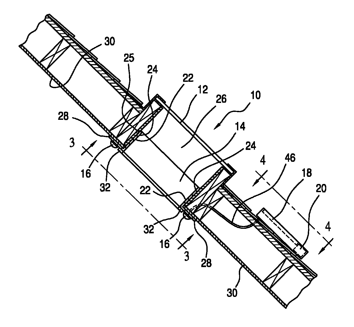
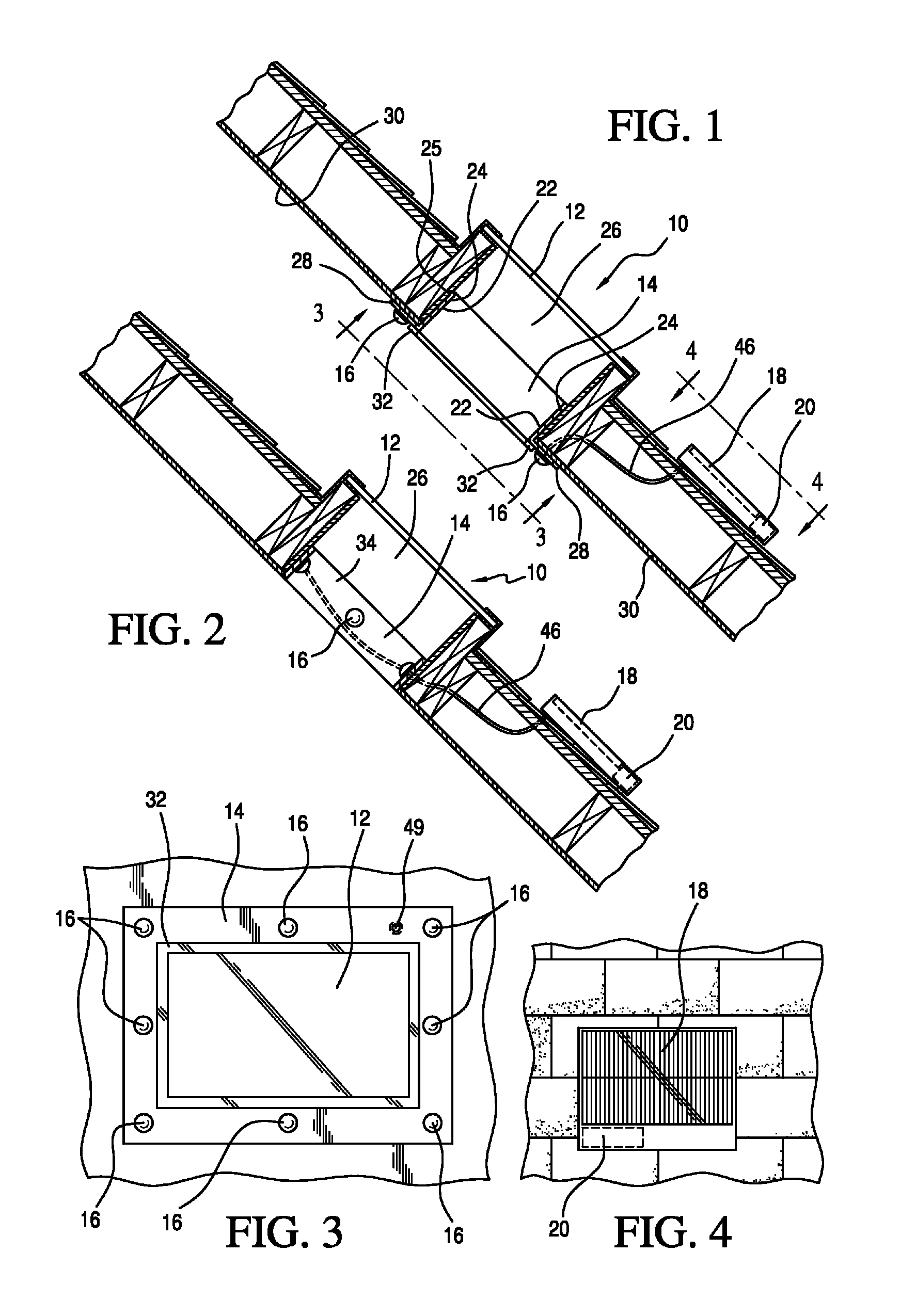
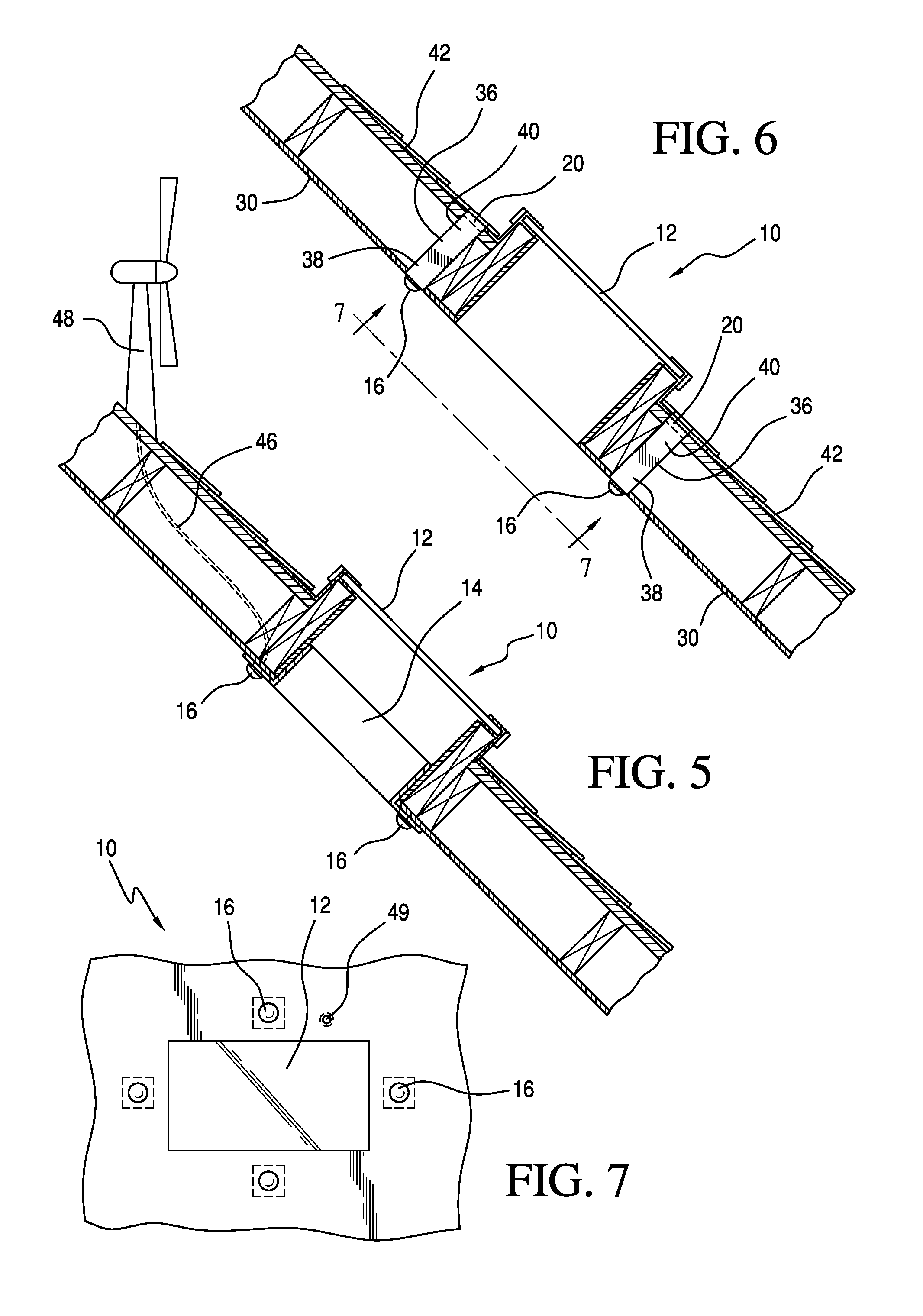
[0032]Referring to the Figures, FIGS. 1-6 show a renewably energy powered light assembly 10 for a skylight 12, having a frame or housing 14 including lighting elements 16, a solar panel 18 or a wind turbine 48, and a rechargeable battery 20. The lighting ele...


PUM


Abstract

The invention is a renewable energy powered light assembly for a roof window of a building. A housing extends within the roof aperture from an interior of the house towards the exterior. A plurality of lighting elements is disposed in the housing. A renewable energy source is connected to each of the lighting elements. A solar panel array collects light from an electrical grid powered lighting element. A rechargeable power source is connected to the renewable energy source and the plurality of lighting elements. The invention also is a light assembly for illuminating an area from a floor of a building. A renewable energy source is externally mounted and coupled to a plurality of lighting elements disposed adjacent the floor. A rechargeable power source is coupled to the energy source and the plurality of lighting elements for storing the power generated and powering the plurality of lighting elements.

Description

CROSS-REFERENCE TO RELATED APPLICATIONS[0001]None.STATEMENT REGARDING FEDERALLY SPONSORED RESEARCH OR DEVELOPMENT[0002]None.REFERENCE TO A “SEQUENCE LISTING”[0003]Not applicable.BACKGROUND OF THE INVENTION[0004]1. Field of the Invention[0005]The present invention relates generally to a light assembly and more particularly to a renewable energy powered light assembly for a window or wall of a building.[0006]2. Description of Related Art[0007]Over recent years, there has been volatility in the price of electricity. In addition to price volatility, the use of certain fuels has been found to be harmful to the environment. For example, when electricity is generated from coal, large amounts of carbon dioxide are emitted into the environment, which contributes to poor air quality and global warming. As a result, many are interested in using alternative energy sources which are less expensive and more environmentally friendly. One type of alternative energy source that is becoming increasin...

Claims


Application Information

Patent Timeline
Patent Type & Authority Patents(United States)
IPC IPC(8): F21S8/00
CPCF21V23/0442F21S19/005F21S9/043F21S9/035F21Y2101/02F21S11/00F21S9/026F21Y2115/10
Inventor CUMBERLAND, HOLLY, S.
Owner CUMBERLAND HOLLY S
Learn More