Lens cleaning mechanism, projection lens, and projection type display device

a technology of projection lens and cleaning mechanism, which is applied in the direction of vehicle cleaning, camera filters, instruments, etc., can solve the problems of insufficient prevention of occurrence of a reduction in brightness or variations in brightness of images to be projected, and difficult to remove micro dust particles adhering to the lens surface or dust particles or the like containing moisture, etc., to achieve the effect of improving performan

Inactive Publication Date: 2014-04-22
NEC DISPLAY SOLUTIONS LTD
View PDF12 Cites 0 Cited by
  • Summary
  • Abstract
  • Description
  • Claims
  • Application Information

AI Technical Summary

Benefits of technology

[0017]It is an object of the present invention to provide a lens cleaning mechanism, a projection lens, and a projection type display device that have improved performance for removing dust particles or the like adhering to a lens surface.

Problems solved by technology

However, when projection type display devices are installed in an environment where there are a lot of dust particles or the like, a lot of dust particles or the like adhere to the surface of the projection lens that is being used.
However, in this lens cleaning mechanism, although large dust particles or the like adhering to the lens surface with a weak force such as static electricity can be removed, it is difficult to remove micro dust particles adhering to the lens surface or dust particles or the like containing moisture.
Furthermore, it is particularly difficult to remove oily dust particles or the like.
As described above, since projection type display devices having a non-contact type lens cleaning mechanism have insufficient power to remove the dust particles or the like adhering to the surface of the projection lens, sometimes the occurrence of a reduction in brightness or variations in bright of the images to be projected cannot be sufficiently prevented.
However, in projection type display devices having this lens cleaning mechanism, when the cleaning operation is performed during use of the device, the wiper obstructs the lens surface to affect the images to be projected.
Therefore, in such contact type lens cleaning mechanisms, it is sometimes necessary to reduce the area of the cleaning unit that obstructs the lens surface or to reduce the number of times and the period of time during which the cleaning unit obstructs the lens surface during the cleaning operation.
Providing this kind of lens cleaning mechanism results in expensive costs.
Therefore, the size of devices that are provided with this lens cleaning mechanism increases.
In addition, since only one end of the wiper is supported by the lens frame, the pressing force of the wiper against the lens surface is strong in the portion on one end side of the wiper, which is supported by the lens frame, whereas the force is weak in the portion on the other end side, which is not supported by the lens frame.

Method used


Image

  • Lens cleaning mechanism, projection lens, and projection type display device
  • Lens cleaning mechanism, projection lens, and projection type display device
  • Lens cleaning mechanism, projection lens, and projection type display device

Examples


Embodiment Construction

[0031]Next, an embodiment of the present invention will be described with reference to the drawings.

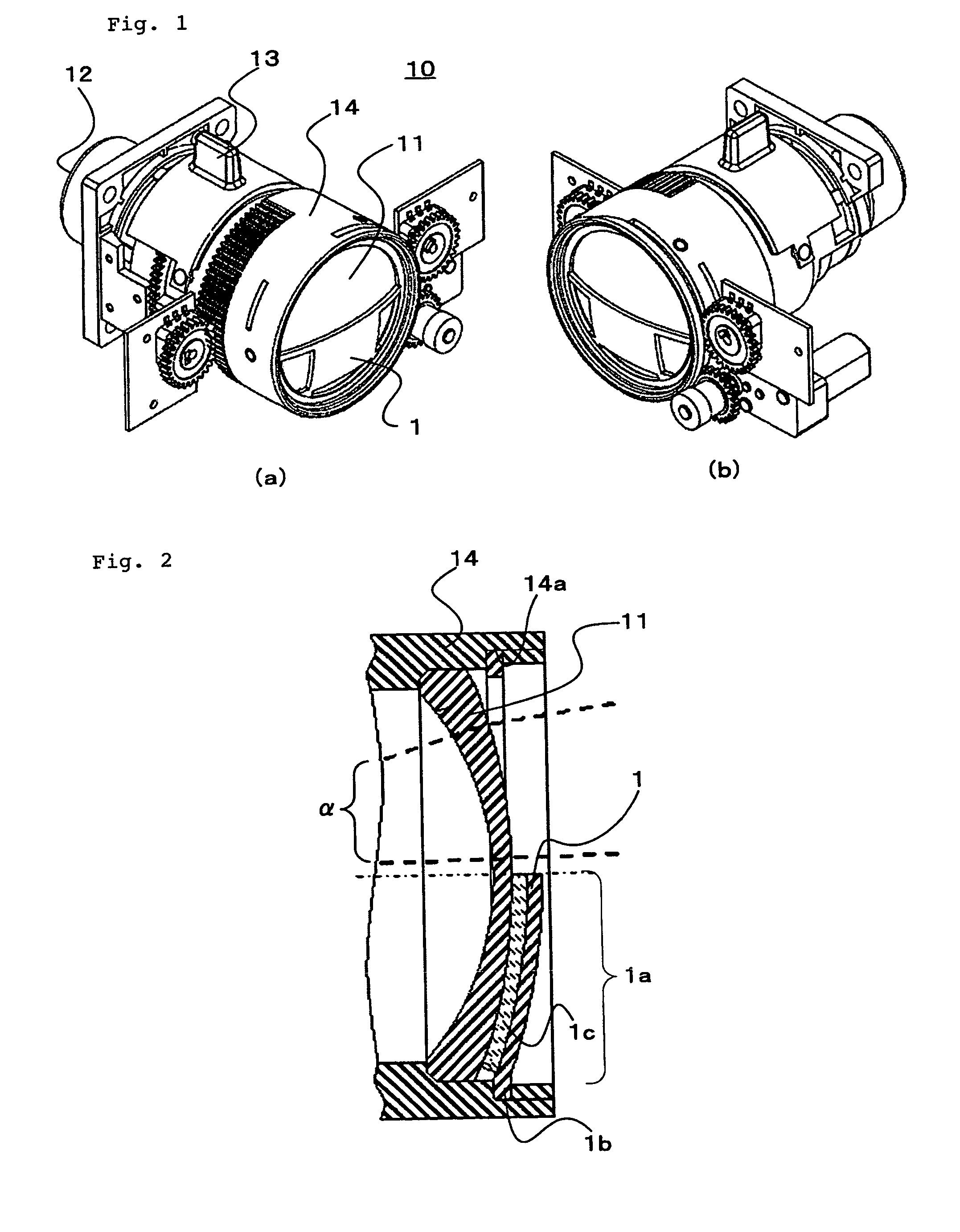
[0032]FIG. 1 shows perspective views of a projection lens having a lens cleaning mechanism according to an embodiment of the present invention.

[0033]Projection lens 10 comprises front lens element 11 that is a lens disposed in the front most part, and rear lens element 12 that is a lens disposed in the rearmost part. Projection lens 10 projects images on a screen or the like by emitting image light, which is incident from rear lens element 12, from front lens element 11.

[0034]Moreover, projection lens 10 comprises zoom lever 13 and focus ring 14 for adjusting images to be projected. The size of an image projected by projection lens 10 is first adjusted by zoom lever 13, and then the focal point is adjusted by focus ring 14, whereby the image having an appropriate size is in proper focus.

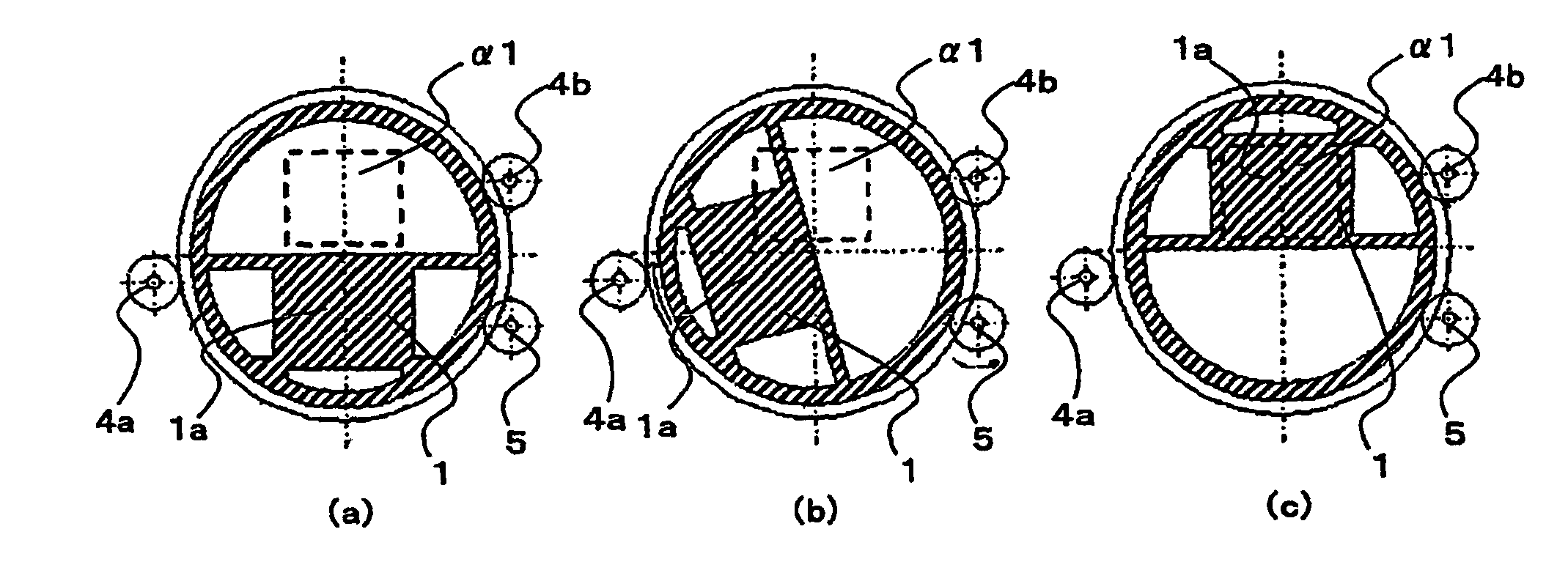
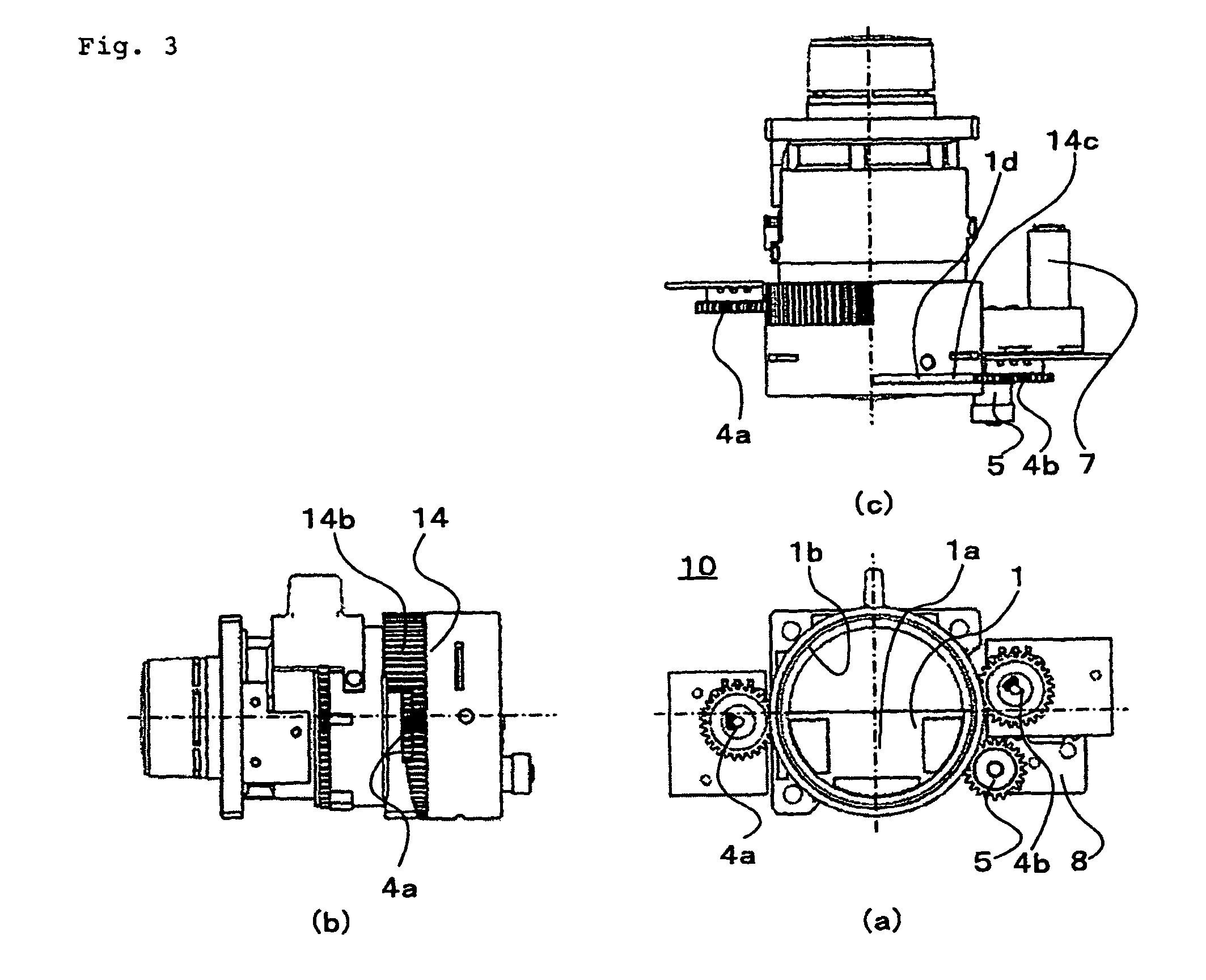
[0035]The lens cleaning mechanism according to this embodiment comprises rotational cleaning plate ...


PUM


Abstract

A lens cleaning mechanism according to the present invention comprises: a cleaning unit (1a) that covers a standby area being a part of the surface of a front lens element (11), as the standby area is pressed, the cleaning unit (1a) being rotationally moved along the surface of the front lens element (11) to slide over the entire surface of the front lens element (11), including a remaining part of the surface and the standby area; a drive unit (3) connected to a holding member (1b); and a control unit (2) for rotationally moving the cleaning unit (1a) by driving the drive unit (3).

Description

TECHNICAL FIELD[0001]The present invention relates to a lens cleaning mechanism, a projection lens, and a projection type display device.BACKGROUND ART[0002]In recent years, the use of projection type display devices has become widespread, and in addition to their installation in conference rooms or the like for use in presentations and the like, they are increasingly installed for use in an environment where there are a lot of dust particles or the like such as stores, outdoors, etc. For projection type display devices installed in an environment where there are a lot of dust particles or the like, dust particles or the like sometimes adhere to the surface of the projection lens (i.e., the surface of a lens disposed at the front most part in a plurality of lenses of the projection lens). When dust particles or the like adhere to the surface of the projection lens, a reduction in brightness or variations in brightness occur in images projected by projection type display devices.[000...

Claims


Application Information

Patent Timeline
Patent Type & Authority Patents(United States)
IPC IPC(8): B60S1/02
CPCG03B21/14G03B11/00G02B27/0006G03B21/145
Inventor OKAZAWA, SHUNSUKEOKADA, TAKAYUKI
Owner NEC DISPLAY SOLUTIONS LTD
Why Eureka
Try Eureka