Thermomagnetic generator

a generator and thermomagnetic technology, applied in the field of thermomagnetic generators, can solve the problems of low efficiency and liquid use efficiency of thermomagnetic generators

Inactive Publication Date: 2014-05-20
DELTA ELECTRONICS INC
View PDF1 Cites 53 Cited by
  • Summary
  • Abstract
  • Description
  • Claims
  • Application Information

AI Technical Summary

Problems solved by technology

Thus, since the hot and cold liquids can not be continuously and simultaneously used, utility of the liquid and efficiency of the thermomagnetic generator is low.

Method used


Image

  • Thermomagnetic generator
  • Thermomagnetic generator
  • Thermomagnetic generator

Examples


Embodiment Construction

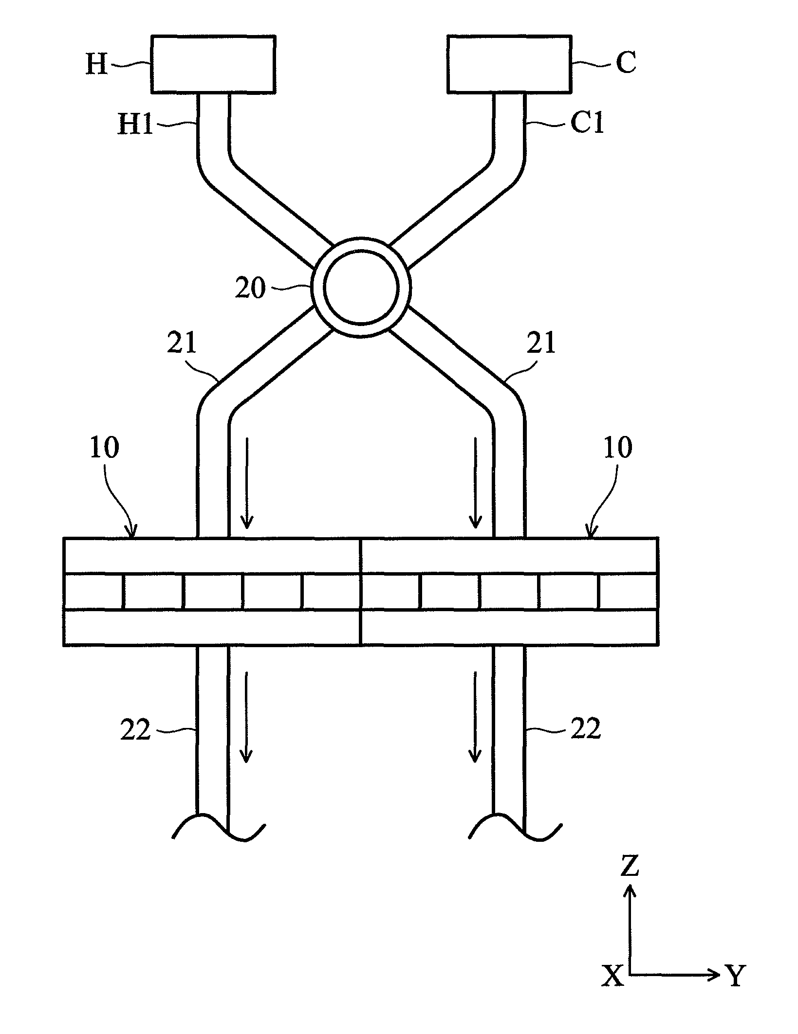
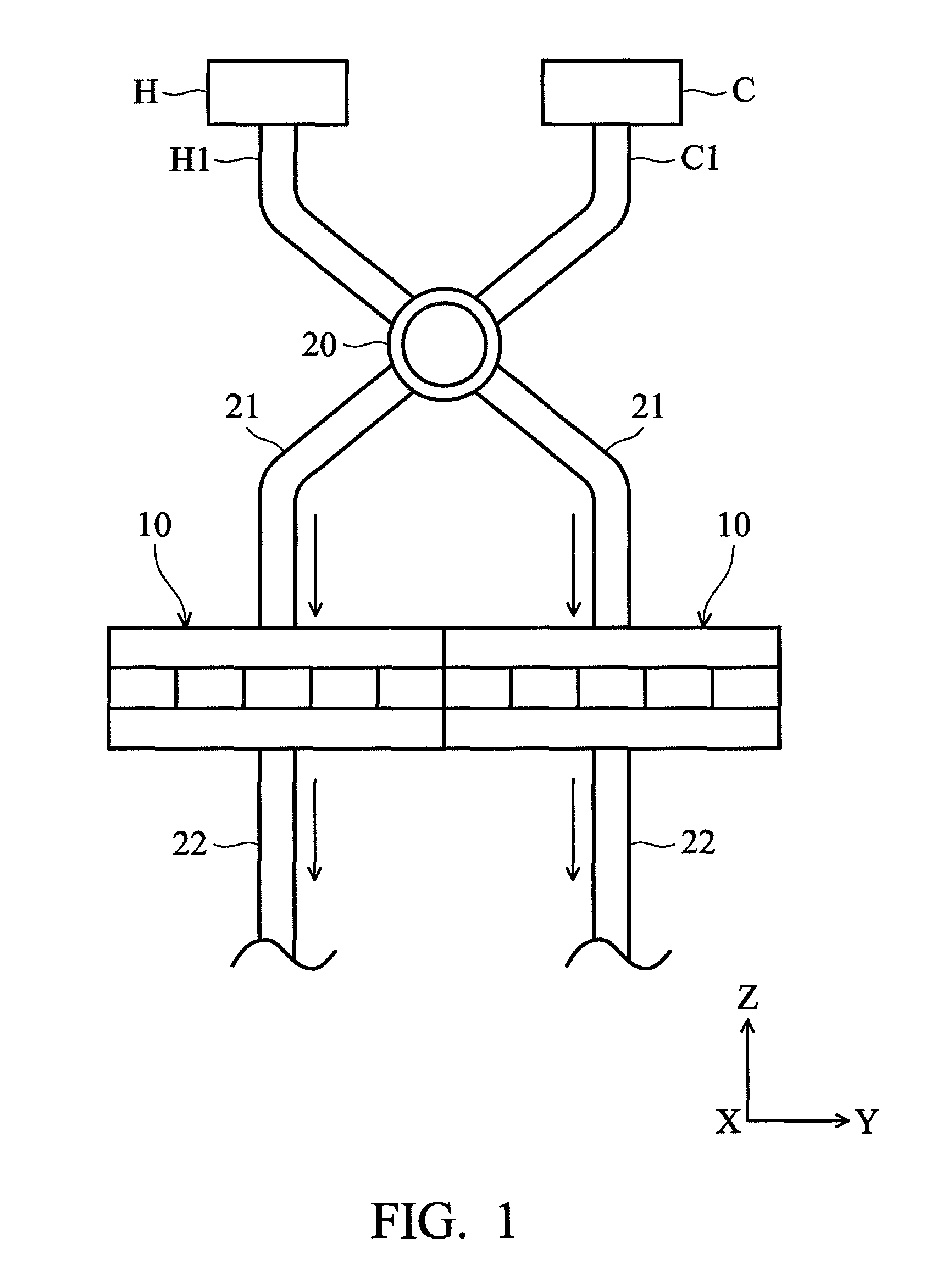
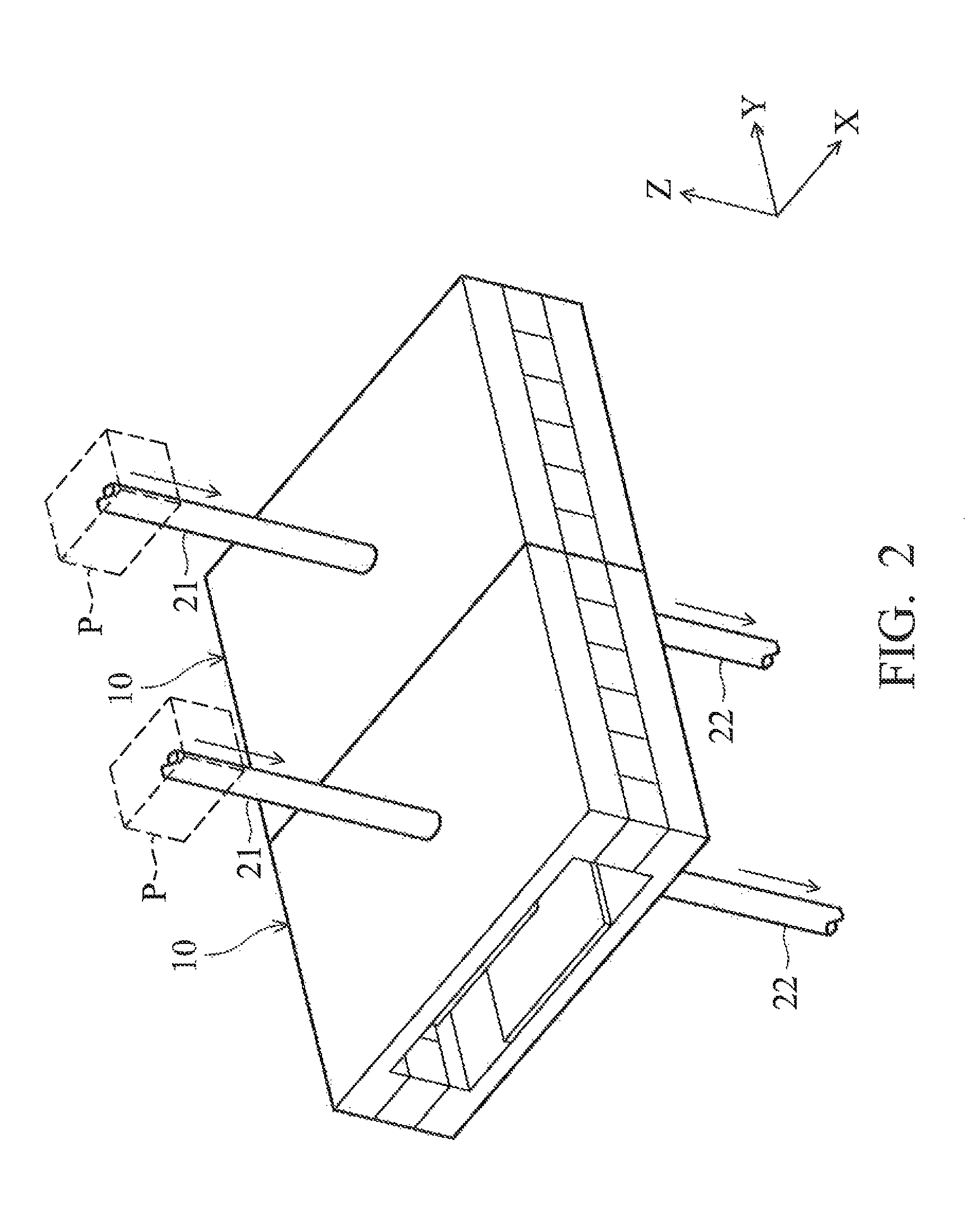
[0013]FIG. 1 depicts an embodiment of a thermomagnetic generator which comprises a hot liquid source H, a hot liquid pipe H1, a cold liquid source C, a cold liquid pipe C1, a switch valve 20, two inlet pipes 21, two magnetic circuit units 10 arranged side by side, and two outlet pipes 22. As shown in FIG. 1, the hot and cold liquid pipes H1 and C1, respectively, extend from the hot and cold liquid sources H and C to the switch valve 20. Additionally, the two inlet pipes 2, respectively, extend from the switch valve 20 to the two magnetic circuit units 10.

[0014]In this embodiment, the hot and cold liquids are continuously pumped from the hot and cold liquid sources H and C through the hot and cold liquid pipes H1 and C1 to the switch valve 20. During operation, the switch valve 20 can individually allow communication of the hot liquid pipe H1 with one of the inlet pipes 21 at the left side, and communication of the cold liquid pipe C1 with the other inlet pipe 21 at the right side fo...


PUM


Abstract

A thermomagnetic generator is provided, including a switch valve, a plurality of magnetic circuit units, a coil, and a plurality of inlet pipes connecting the magnetic circuit units to the switch valve. Each of the magnetic circuit units includes a magneto-caloric member. The switch valve repeatedly and alternatively switches at a predetermined frequency to guide hot and cold fluids to the magnetic circuit units, such that the magneto-caloric members are magnetized and demagnetized, respectively, by the cold and hot fluids. The coil is coupled to at least one of the magnetic circuit units for obtaining an induced voltage.

Description

BACKGROUND OF THE INVENTION[0001]1. Field of the Invention[0002]This application relates in general to a thermomagnetic generator and in particular to a thermomagnetic generator applying hot and cold liquids.[0003]2. Description of the Related Art[0004]Thermomagnetic generators are devices that convert heat into electrical energy. They utilize the magnetic and magneto-caloric properties of magneto-caloric material which changes rapidly with temperature near a magnetic phase transition temperature, such as a Curie temperature. The magneto-caloric material is conventionally provided in a magnetic circuit. A coil or resonant circuit may be provided near the magnetic circuit for obtaining an induced voltage.[0005]A temperature-varying device is usually provided in the thermomagnetic generator for varying the temperature of the magneto-caloric material. The temperature-varying device may apply hot and cold liquids through individual pipes to change the temperature of the magneto-caloric ...

Claims


Application Information

Patent Timeline
Patent Type & Authority Patents(United States)
IPC IPC(8): F02B71/04H01L37/04F02B63/04H02K35/02H03G7/08H02N11/00F03G7/08H02K7/18H02N10/00
CPCH02K7/1853H01L37/04H02K35/02H02N11/00H02N10/00F02B63/04H03G7/08F02B71/04H10N15/20
Inventor KUO, CHUNG-JUNGMAO, TZE-CHERNHSIEH, SHENG-FANLIN, MING-TSZHSIAO, FU-CHOUSHIH, CHENG-YENHSU, MAO-JEN
Owner DELTA ELECTRONICS INC
Why Eureka
Try Eureka