
Display device, electronic device and image processing apparatus including the display device, and method of displaying information

a technology of electronic devices and display devices, applied in the direction of digital output to print units, visual presentations, instruments, etc., can solve the problems of waste of consumables (toner and recording paper), user cannot confirm the finished form, output is a failed copy, etc., and achieve the effect of accurate presentation to the user

Active Publication Date: 2014-05-27
SHARP KK
View PDF23 Cites 8 Cited by
  • Summary
  • Abstract
  • Description
  • Claims
  • Application Information

AI Technical Summary

Benefits of technology

[0024]In the display device, the planar display area has an approximately rectangular shape. Therefore, by adjusting the width of the first and second display areas in the longitudinal direction of the planar display area, the size of the first and second display areas can be changed in a flexible manner. For instance, if the amount of first information is large, the width of the first display area can be made wider (and the width of the second display area becomes narrower as a result), and the first information of large amount can accurately be given to the user. On the other hand, if the amount of second information is large, the width of the second display area can be made wider (and the width of the first display area becomes narrower as a result), and the second information of large amount can accurately be given to the user. Even if the amount of preview information and the amount of setting information vary, the preview information and the setting information required by the use can accurately be presented to the user. Assume, for example, that the apparatus as the object of control is an apparatus that executes a process of printing a plurality of documents. Then, the setting function includes functions intended for a plurality of pages and functions intended for a single page. When a function intended for a plurality of pages is used, it becomes necessary to show the result of processing of the plurality of pages as a preview and, therefore, the amount of preview information tends to increase. In such a case, the manner of display of the first information is changed to make wider the second display area, so that the preview information of large amount can be displayed accurately.
[0026]In order to set a function of the apparatus as the object of control, icons and / or pieces of function information are prepared. Each piece of function information is larger in size than each icon. Therefore, when the first information is displayed in the first manner of display (icons only), the first display area can be made narrower than when it is displayed in the second manner of display (which includes at least the function information and may or may not include icons). If the amount of preview information is large, it is possible to display the first information in the first manner of display to make narrower the first display area and to make wider the second display area, so that the preview information of large amount can accurately be displayed.
[0034]In the electronic device and the image processing apparatus, the display device provided therein has an approximately rectangular planar display area. By adjusting the width of the first and second display areas in the longitudinal direction of the planar display area, the size of the first and second display areas can be changed in a flexible manner. As a result, information related to the electronic device and the image forming apparatus can be presented accurately to the user.
[0044]By the present invention, when a result of processing based on functions set in an electronic device and an image processing apparatus (image forming apparatus) is displayed as a preview before actual processing, the preview information and the function setting information required by the user can accurately be presented to the user.

Problems solved by technology

If such a finish function or functions are set for printing, the user cannot confirm the finished form until he / she obtains the result of actual printing.
Therefore, it is not unusual that a user sets a finish with punched holes and when actually printed, the output is a failed copy having images overlapped with the positions of holes to be punched.
This leads to waste of consumables (toner and recording paper).
However, if a large area is necessary for displaying preview information (for example, if previews of a plurality of pages are to be displayed to determine layout of a plurality of documents), it is impossible to fully present the preview information to the user with a small preview screen image.
On the other hand, if the preview screen image is large while only a small area is necessary to display the preview information (for example, when a preview of one page is displayed to carry out image processing of a single document), an area for presenting editing functions to the user becomes too small, and it is impossible to fully present the function selection information to the user.
Therefore, even when the amount of information required for appropriately giving the preview information to the user changes, or when the amount of information required for appropriately giving the function setting information to the user changes, the size of preview area and the size of function selecting area are fixed and, hence, the problem that necessary information cannot fully be given to the user remains unsolved.
Further, none of the references described above discloses changing the manner of displaying the preview or the manner of displaying the function selection menu in accordance with an operation by the user, in order to facilitate the next operation by the user, and changing the manner of displaying the preview or the manner of displaying the function selection menu in order to facilitate confirmation of the result of operation by the user.

Method used


Image

  • Display device, electronic device and image processing apparatus including the display device, and method of displaying information
  • Display device, electronic device and image processing apparatus including the display device, and method of displaying information
  • Display device, electronic device and image processing apparatus including the display device, and method of displaying information

Examples


Embodiment Construction

[0064]In the following description, the same components are denoted by the same reference characters. Their names and functions are also the same. Therefore, detailed description thereof will not be repeated.

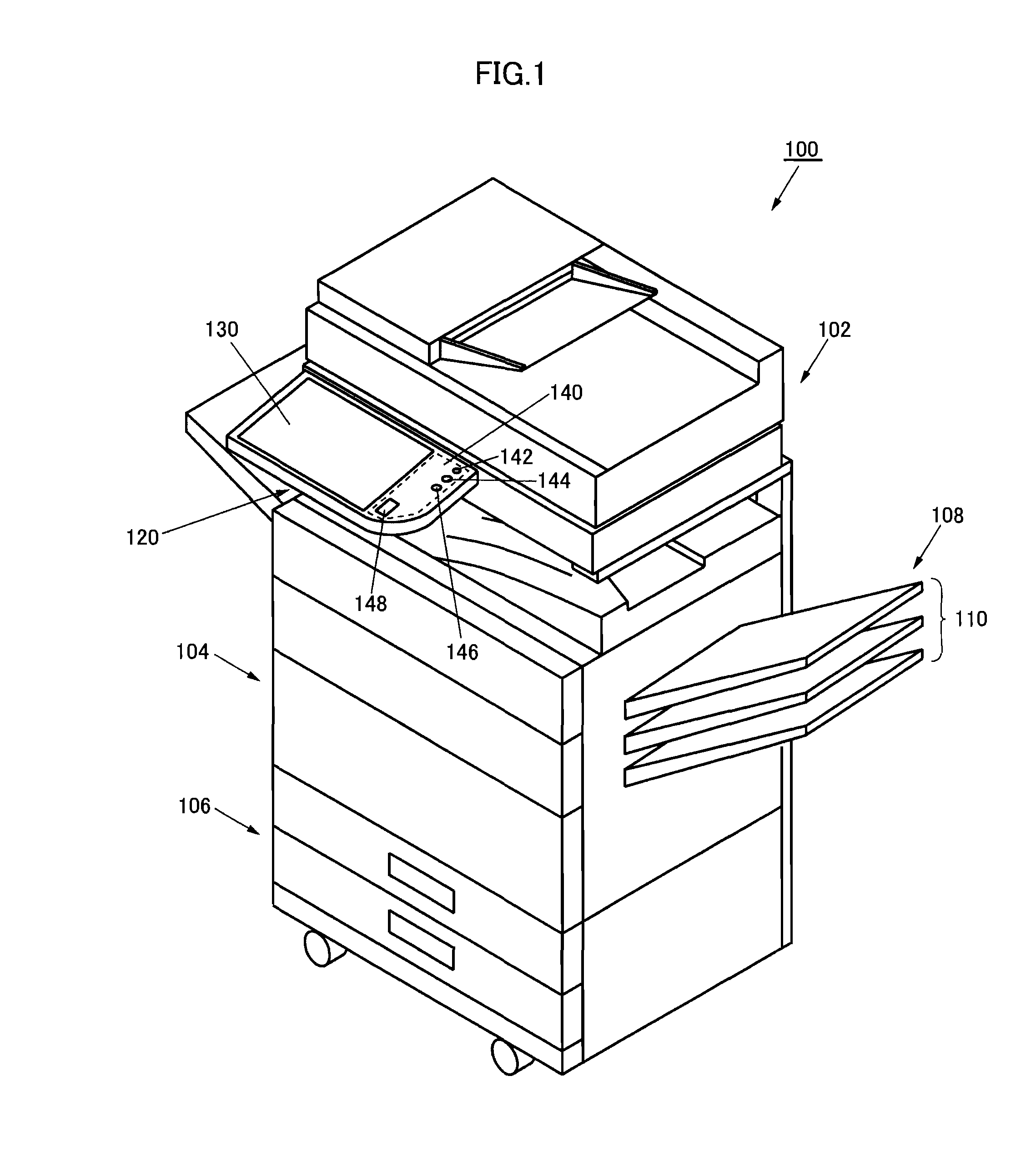
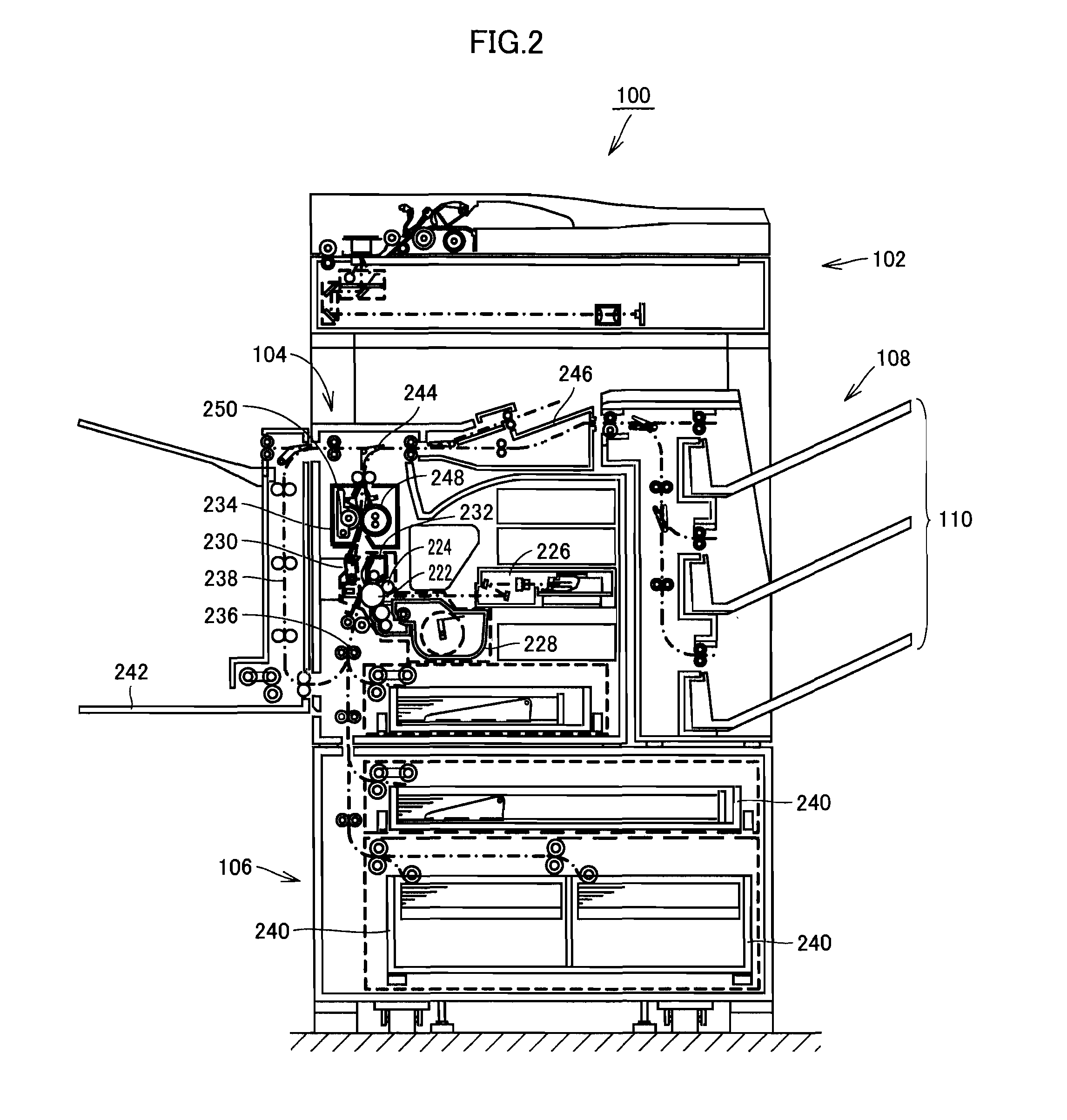
[0065]The electronic device in accordance with an embodiment of the present invention is an image forming apparatus as one type of image processing apparatuses. The display device in accordance with the present invention may be applicable to an image processing apparatus or an electronic device other than the image forming apparatus. The electronic device in accordance with the present embodiment may be any apparatus having a plurality of operational modes and provided with the display device having two or more display modes for suitably changing the size of areas for displaying information so that when, at least in one of the operational modes, a function selection menu (information displayed on a function setting / confirmation area 2000 as will be described later) and preview i...


PUM


Abstract

On a touch-panel display of an image forming apparatus, a function selecting area and a preview area are displayed next to each other. On the function selecting area, a function setting menu is displayed in one display mode among an icon mode in which only a group of icons are displayed, a regular mode in which a group of icons and a group of texts are displayed, and an express mode in which a group of icons, a group of texts and a group of function setting buttons are displayed. In the icon mode, detailed preview information is displayed on a large preview area, and in the express mode, detailed function selecting information is displayed on a large function selecting area.

Description

CROSS-REFERENCE TO RELATED APPLICATION[0001]This nonprovisional application claims priority under 35 U.S.C. §119(a) on patent application Ser. No. 2010-025495 filed in Japan on Feb. 8, 2010, the entire contents of which are hereby incorporated by reference.BACKGROUND OF THE INVENTION[0002]1. Field of the Invention[0003]The present invention relates to a display device that allows, even if an operational mode of an electronic device or an image processing apparatus is changed and screen images are switched accordingly, the user to appropriately grasp the pieces of information displayed in each operational mode. Particularly, the present invention relates to a display device capable of presenting, when the screen image is divided into a plurality of areas for displaying function setting information and preview information (though not limited to these pieces of information), the function setting information and the preview information in an appropriate manner by changing the size of ar...

Claims


Application Information

Patent Timeline
Patent Type & Authority Patents(United States)
IPC IPC(8): G06F3/12G06F3/048G06F3/0481G06F3/0482G06F3/0488
CPCH04N2201/0094H04N1/00482H04N1/00474H04N1/00427H04N1/00456H04N1/00448H04N1/00442H04N1/00424H04N1/00453H04N1/00411H04N1/00381H04N1/00413H04N1/00506H04N1/0044G06F3/0414G06F3/0416G06F3/1297G06K15/00G06F3/017G06F3/04817G06F3/0488G06F3/04847G06F3/04883G06F3/04886
Inventor SENSU, MINAMIEBI, YUKARI
Owner SHARP KK
Learn More