Linear cutting and stapling device with selectively disengageable cutting member

a cutting member and stapling device technology, applied in the field of surgical cutting and stapling instruments, can solve the problems of inability to move the anvil, and the height of the formed staple cannot be adjusted

Active Publication Date: 2014-07-29
ETHICON ENDO SURGERY INC
View PDF1372 Cites 1307 Cited by
  • Summary
  • Abstract
  • Description
  • Claims
  • Application Information

AI Technical Summary

Benefits of technology

[0009]In accordance with other general aspects of the present invention, there is provided a surgical staple cartridge for use with a surgical stapling instrument that has an end effector with first and second jaw members for clamping tissue therebetween. The surgical stapling instrument also has a knife bar assembly for generating a cutting motion and a pusher bar arrangement for generating a staple firing motion that is independent from the cutting motion. Various embodiments of the staple cartridge comprise a cartridge body that is configured to be removably supported in the end effector. The cartridge body operably supports a plurality of staples that are oriented in plural longitudinally extending rows and are configured to be ejected therefrom upon application of the staple firing motion thereto. A cutting blade is operably supported in the cartridge body and is selectively movable from an unactuated position at a first end of the cartridge body to an actuated position at a second end of the cartridge body upon application of the cutting motion thereto. The cutting blade is configured to selectively remain in the unactuated position during the application of the firing motion to all of the staples and move from the unactuated position to the actuated position upon application of the cutting motion thereto.

Problems solved by technology

In typical stapling instruments, however, the anvil is unmovable relative to the staple cartridge once the jaw members have been assembled together and the formed height of the staples cannot be adjusted.

Method used


Image

  • Linear cutting and stapling device with selectively disengageable cutting member
  • Linear cutting and stapling device with selectively disengageable cutting member
  • Linear cutting and stapling device with selectively disengageable cutting member

Examples


Embodiment Construction

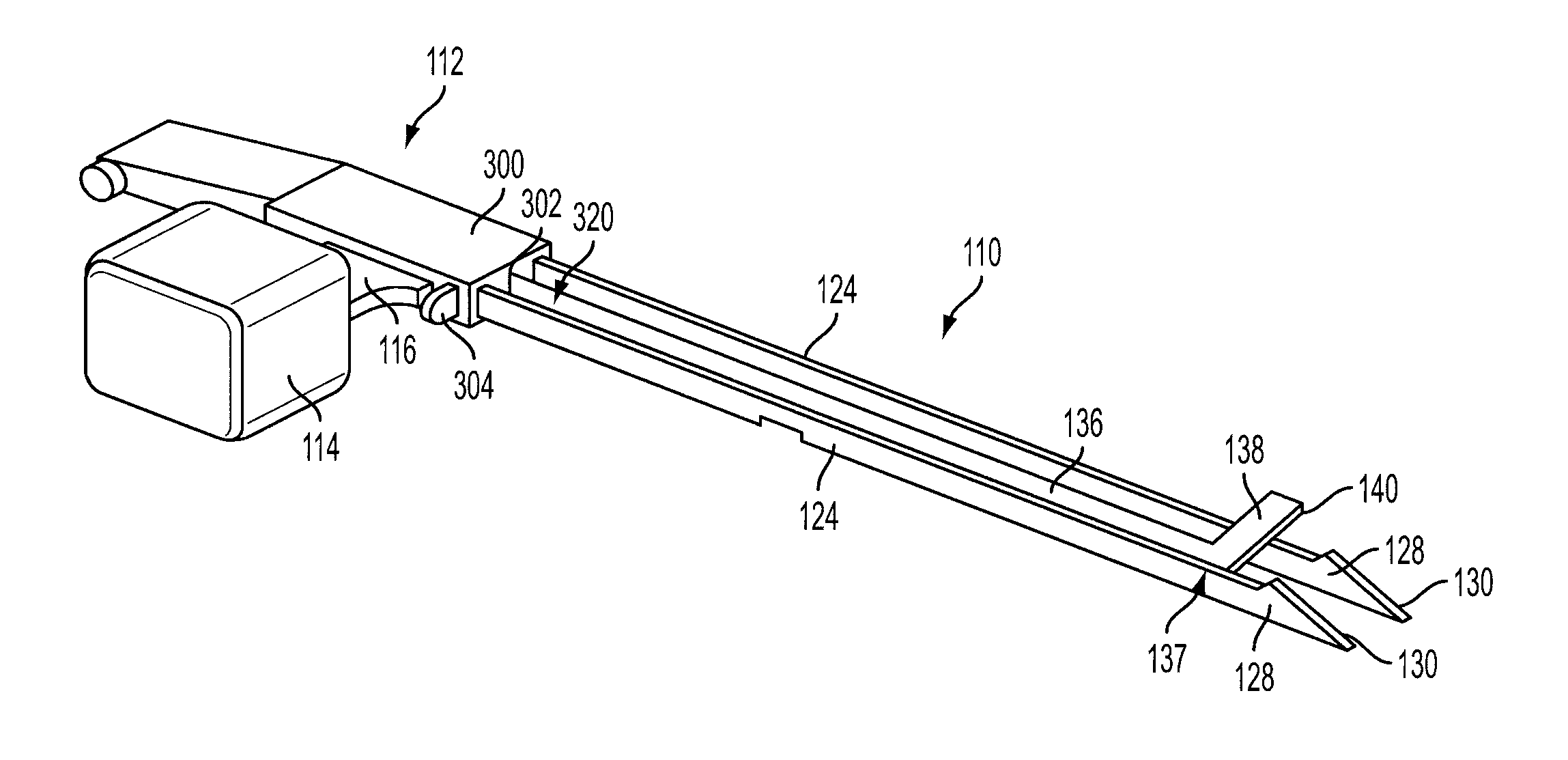
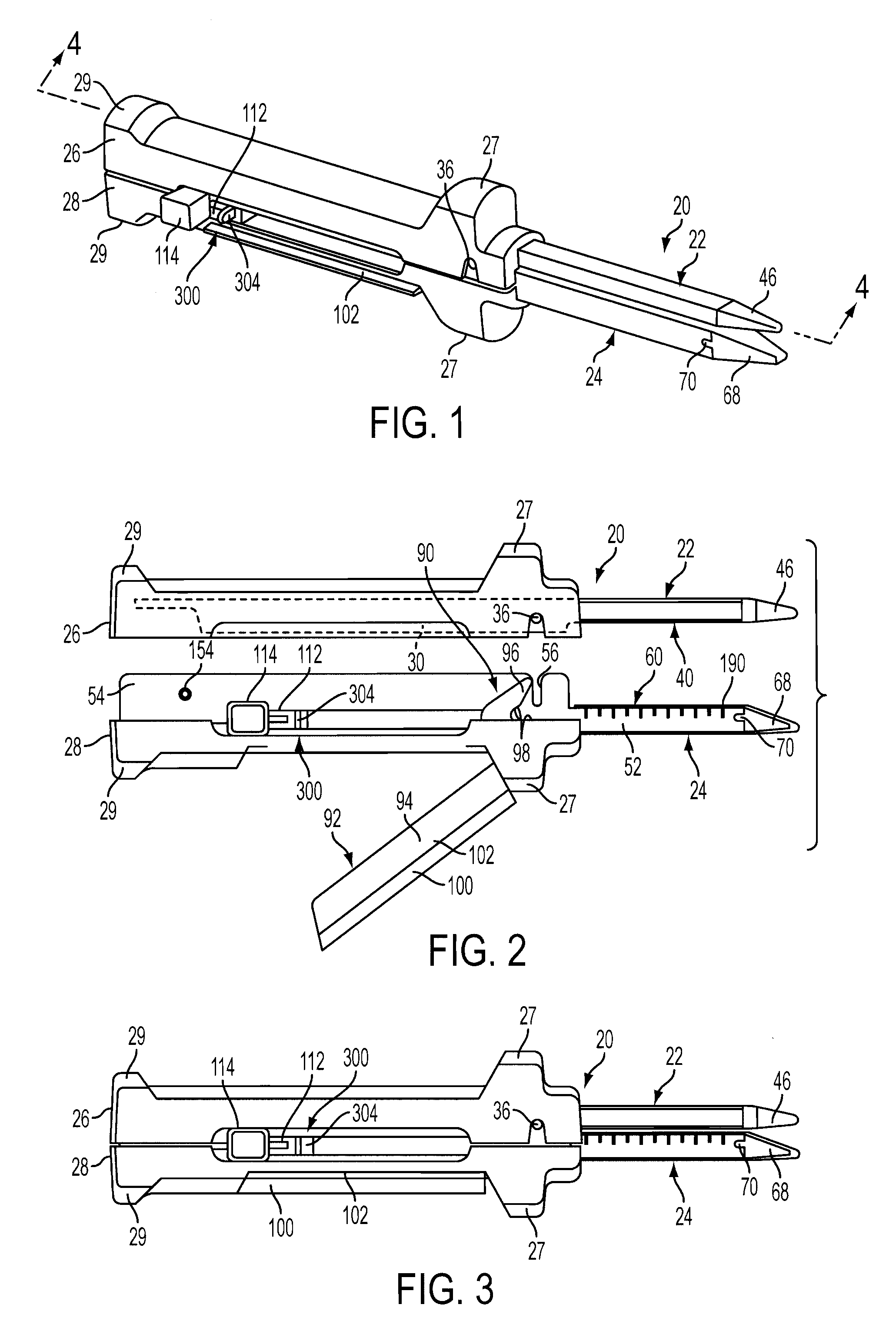
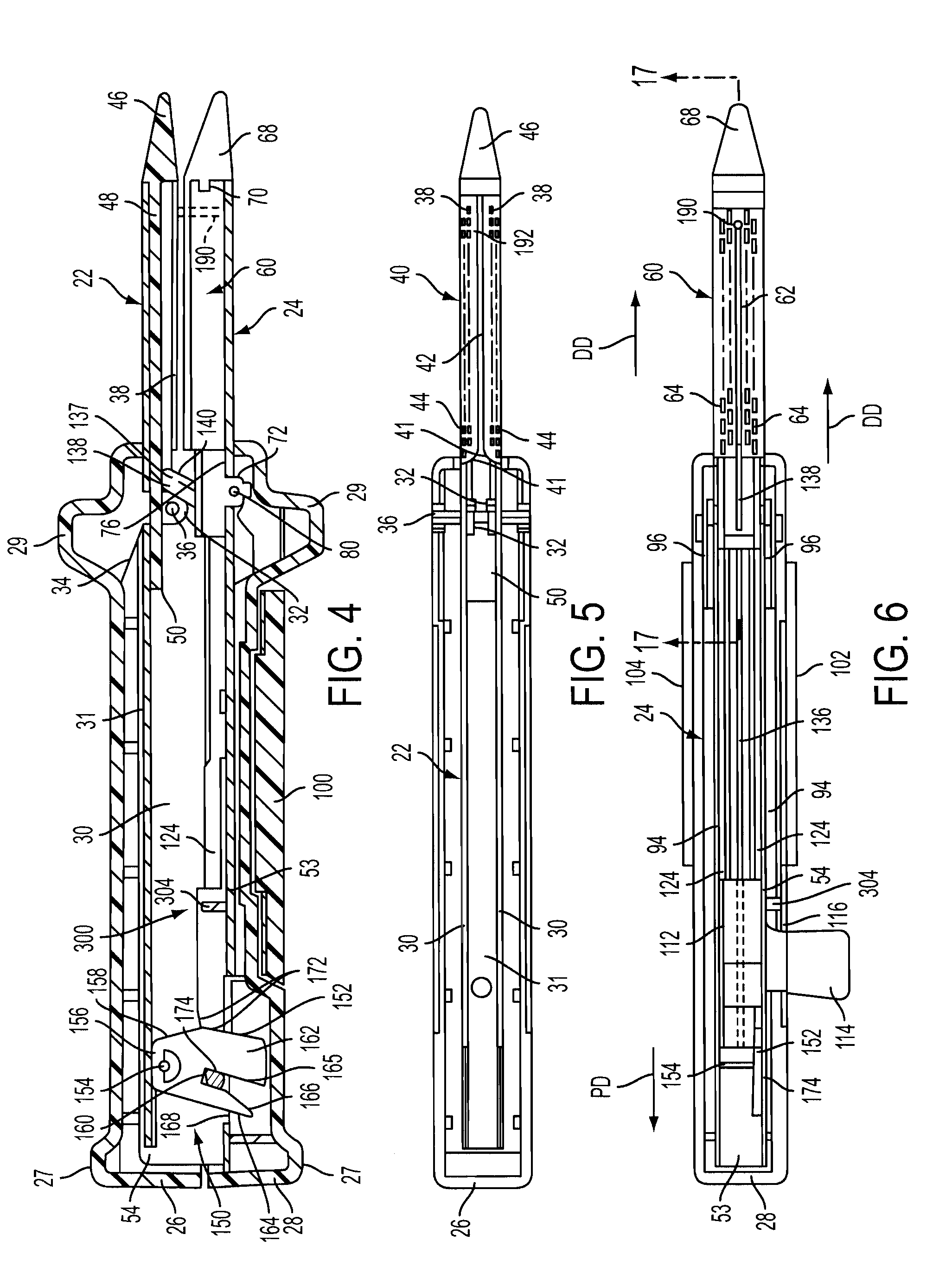
[0037]Certain exemplary embodiments will now be described to provide an overall understanding of the principles of the structure, function, manufacture, and use of the devices and methods disclosed herein. One or more examples of these embodiments are illustrated in the accompanying drawings. Those of ordinary skill in the art will understand that the devices and methods specifically described herein and illustrated in the accompanying drawings are non-limiting exemplary embodiments and that the scope of the various embodiments of the present invention is defined solely by the claims. The features illustrated or described in connection with one exemplary embodiment may be combined with the features of other embodiments. Such modifications and variations are intended to be included within the scope of the present invention.

[0038]Reference throughout the specification to “various embodiments,”“some embodiments,”“one embodiment,” or “an embodiment”, or the like, means that a particular...


PUM

PropertyMeasurementUnit
timeaaaaaaaaaa
heightaaaaaaaaaa
structureaaaaaaaaaa

Abstract

A surgical stapling instrument including a selectively actuatable cutting member. The stapling instrument may be used as a surgical stapler without cutting tissue or, if desired, the surgeon may selectively actuate the cutting member to cut tissue as the staples are being deployed and formed. A stapling instrument can include an actuator knob that has at least one pusher bar attached thereto. Advancement of the actuator knob in a distal direction causes the pusher bars to apply a firing motion to the staples contained within a staple cartridge supported within the stapling instrument. A knife bar may be selectively coupleable to the actuator knob by a selector switch that is movable from an actuated position wherein movement of the actuator knob in the distal direction advances the knife bar which has a cutting blade portion to advance between rows of staples in the staple cartridge to an unactuated position wherein movement of the actuator knob advances the pusher bars without advancing the knife bar.

Description

BACKGROUND[0001]1. Technical Field[0002]The present invention relates to stapling instruments and, in various embodiments, to a surgical cutting and stapling instrument for producing one or more rows of staples.[0003]2. Background of the Related Art[0004]In recent years, there has been an increasing tendency for surgeons to use stapling instruments to suture body tissues such as a lung, an esophagus, a stomach, a duodenum and / or other organs in the intestinal tract. The use of an appropriate stapling instrument in many instances may perform a better job in less time and simplify previously difficult surgical procedures such as gastrointestinal anastomoses. Previous linear two and four row cutting staplers comprised cartridge-less instruments into which staples were individually hand-loaded. Other previous devices have included a presterilized disposable staple loading unit and a cutting member which could be utilized for dividing the tissue and forming the rows of staples simultaneo...

Claims


Application Information

Patent Timeline
Patent Type & Authority Patents(United States)
IPC IPC(8): A61B17/068
CPCA61B17/07207A61B2017/07285A61B2017/320052A61L2/081A61L2/082A61L2/087A61L2202/24
Inventor BAXTER, III, CHESTER O.TSONTON, MARK
Owner ETHICON ENDO SURGERY INC
Why Eureka
Try Eureka