Auxiliary power tool handle

a technology of power tools and handles, applied in the direction of fastening means, rod connections, pipes, etc., can solve the problems of difficult control, possible damage to bits or other components held in the working end of the tool, and many power tools produce significant vibration and rotational forces, so as to control the rotational reaction of the tool and apply rotational force and longitudinal force more easily.

Active Publication Date: 2014-08-12
SNAP ON INC
View PDF8 Cites 10 Cited by
  • Summary
  • Abstract
  • Description
  • Claims
  • Application Information

AI Technical Summary

Benefits of technology

[0005]The present application improves upon the conventional power tool handle by providing a handle that can be configured in either a straight or T-shaped position. In the straight position, the handle design serves as a rotational safety control that allows a user to control the rotational reaction of the tool by placing the user's hand in a position that is perpendicular to the main body of the tool. In the T-shaped configuration, the user can apply rotational force and longitudinal force more easily because the hand position is tangent to the tool body.

Problems solved by technology

However, many power tools produce significant vibrations and rotational forces during use, or can otherwise be difficult to control due to the amount of power that is transmitted from the tool to the workpiece or working material.
This configuration encourages the user to apply force on the tool in a direction that is not parallel to the main body of the tool, leading to possible damage of the bits or other components held in the working end of the tool.
Also, the two hands of the user and the cutting point of the tool form a triangle that results in user discomfort and fatigue.
The conventional configuration therefore results in hand and wrist discomfort that ultimately causes the tool bit to bend, twist and break.

Method used


Image

  • Auxiliary power tool handle
  • Auxiliary power tool handle
  • Auxiliary power tool handle

Examples


Embodiment Construction

[0016]While this invention is susceptible of embodiments in many different forms, there is shown in the drawings and will herein be described in detail a preferred embodiment of the invention with the understanding that the present disclosure is to be considered as an exemplification of the principles of the invention and is not intended to limit the broad aspect of the invention to embodiments illustrated.

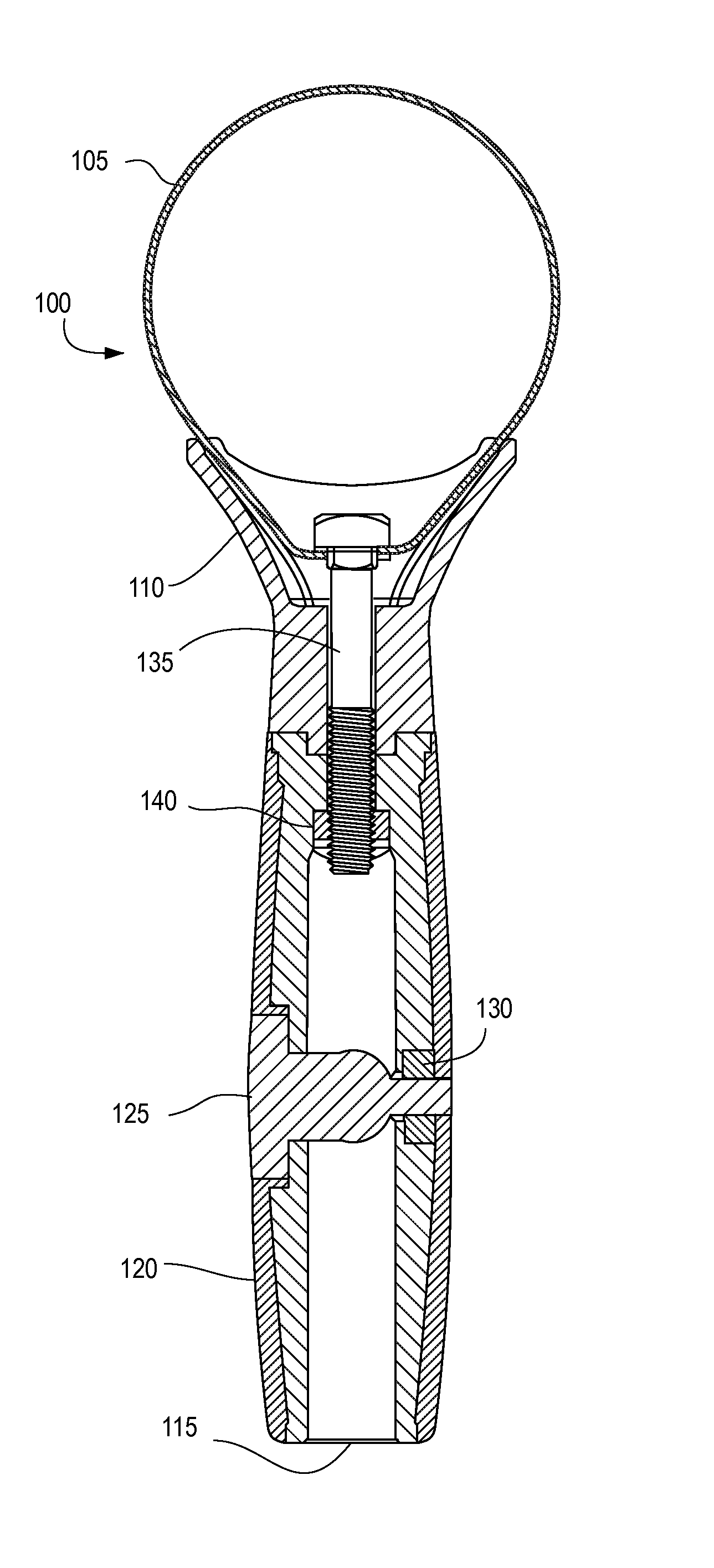
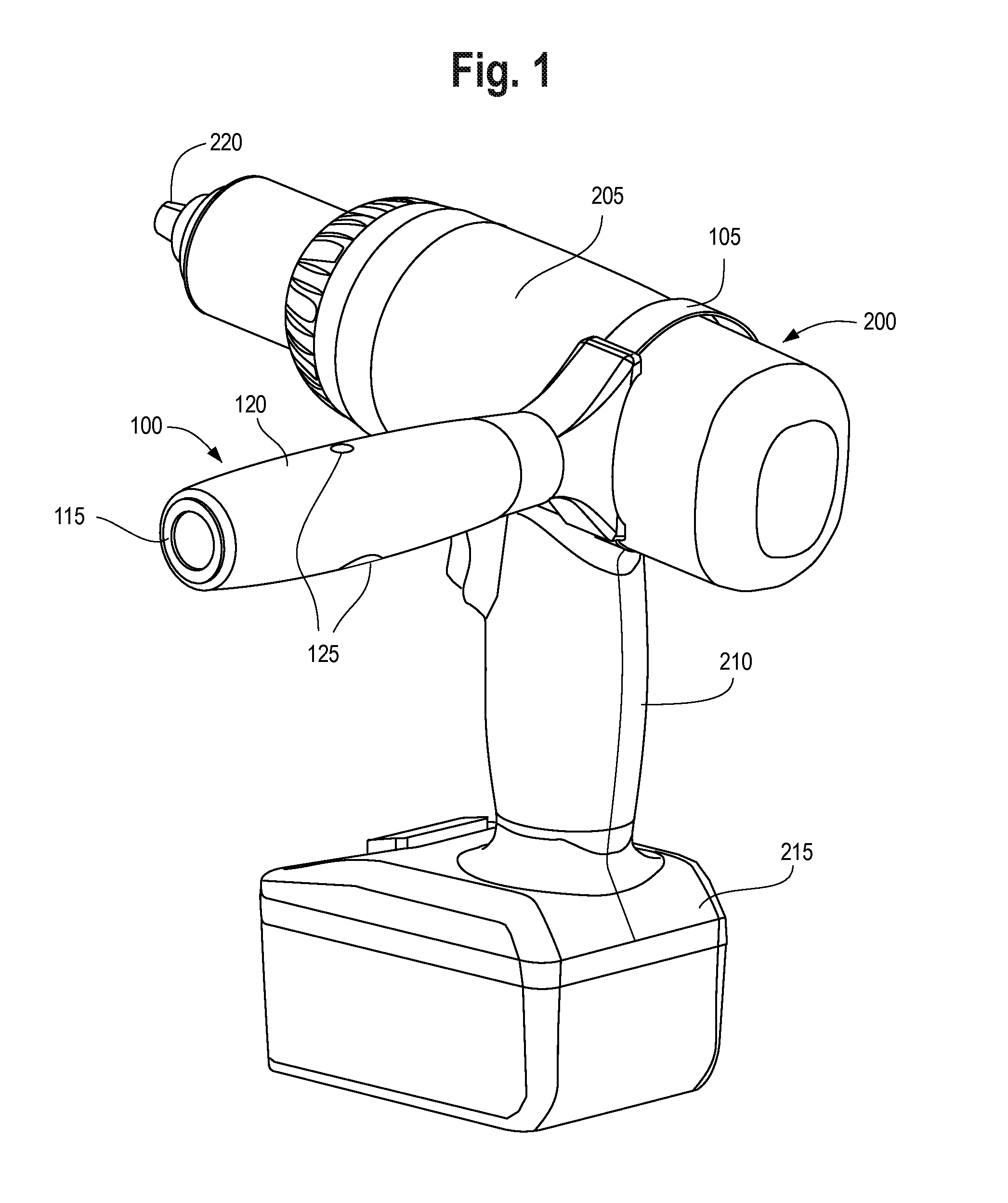
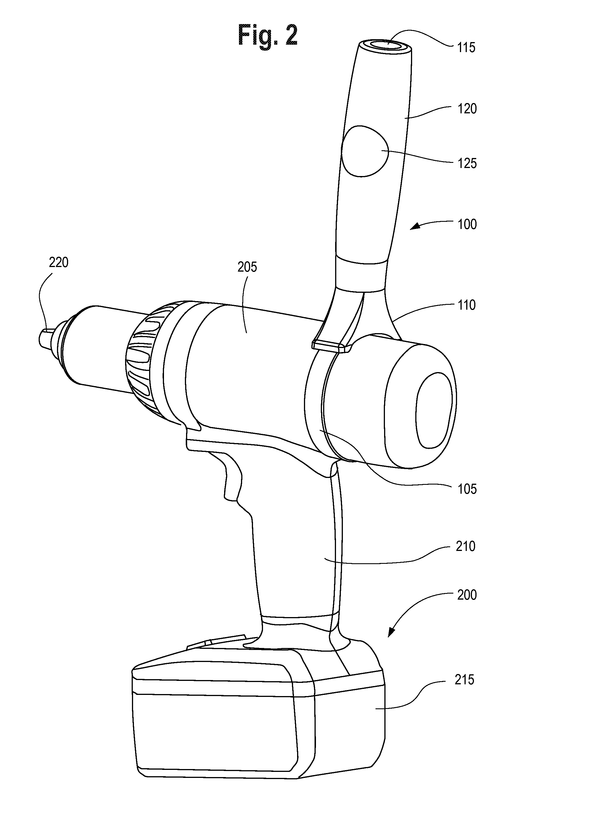
[0017]The present application discloses a handle that can be configured in either a straight or T-shaped position based on user preference. In the straight position, the handle allows the user to control rotational forces of the tool, and in the T-shaped configuration, the user can apply rotational force and longitudinal force more easily because the hand position is tangent to the tool body. The handle is easily adjusted from the straight to T-shaped positions and can also be removed from the power tool if the user so chooses.

[0018]As shown in FIGS. 1-3, the handle 100 is coupled...


PUM


Abstract

A handle for controlling a power tool by configuring the handle in either a straight or T-shaped position. In the straight position, the handle design serves as a rotational safety control that allows a user to control the rotational reaction of the tool by placing the user's hand in a position that is perpendicular to the main body of the tool. In the T-shaped configuration, the user can apply rotational force and longitudinal force more easily because the hand position is tangent to the tool base. A fastener couples a base of the handle to a band that grips the power tool and facilitates the user control.

Description

FIELD OF THE INVENTION[0001]The present application relates generally to a handle for a power tool. More particularly, the present application relates to an auxiliary power tool handle that can be adjusted to either a straight line or T-shaped configuration.BACKGROUND OF THE INVENTION[0002]Power tools are commonly used to complete industrial or home improvement tasks. Many power tools are portable and battery-powered or fuel cell powered, allowing a user to apply considerable torque or force on a workpiece without exerting a substantial amount of energy. However, many power tools produce significant vibrations and rotational forces during use, or can otherwise be difficult to control due to the amount of power that is transmitted from the tool to the workpiece or working material.[0003]Several attempts have been made to resolve the above issue. For example, handles have been developed that allow a user to hold the power tool with one hand, and control the movement of the power tool ...

Claims


Application Information

Patent Timeline
Patent Type & Authority Patents(United States)
IPC IPC(8): F16B9/00B25F5/02B25G3/00
CPCB25F5/026Y10T403/4617Y10T403/4614F16B2/08F16B7/0493F16B2200/403B25G1/00
Inventor GRIFFIN, PAUL, W.
Owner SNAP ON INC
Why Eureka
Try Eureka