Eureka AIR delivers breakthrough ideas for toughest innovation challenges, trusted by R&D personnel around the world.

Filtration system and method of design

a filtration system and filter technology, applied in the field of filtration systems, can solve the problems of adversely increasing the resistance to flow through the filter, and achieve the effect of optimizing the performance of the filtration system

Active Publication Date: 2014-08-19
PARKER INTANGIBLES LLC
View PDF14 Cites 0 Cited by
  • Summary
  • Abstract
  • Description
  • Claims
  • Application Information

AI Technical Summary

Benefits of technology

[0026]Embodiments of the invention further provide the advantage of a simple and low risk solution utilising a combination of different filter media types into a single filtration stage. The prior art approach of developing an entirely new media involves an inherent commercial risk that the new media will not fulfil the desired properties, and combining media in parallel in accordance with the embodiments of the invention avoid such development risks.

Problems solved by technology

Filters are generally subject to accumulation of particulates on and in the filter media over time, which adversely increases resistance to flow through the filters.

Method used


Image

  • Filtration system and method of design
  • Filtration system and method of design
  • Filtration system and method of design

Examples


Embodiment Construction

[0019]Filtration efficiency is defined in terms of the percentage of contaminant particles removed from a flow of fluid by a filter as a function of particle size distribution. Efficiency may increase during use as particulates build up on and in the filter media, but pressure loss increases correspondingly. The life of a filter is defined as the time it takes to load the filter with an amount of contaminant sufficient to give rise to a given pressure loss across the filter. In one example, the maximum acceptable pressure loss is 3 inches of water gauge (623 Pa). The filter life may be further characterized by the occurrence of a sharp increase in pressure drop across the filter.

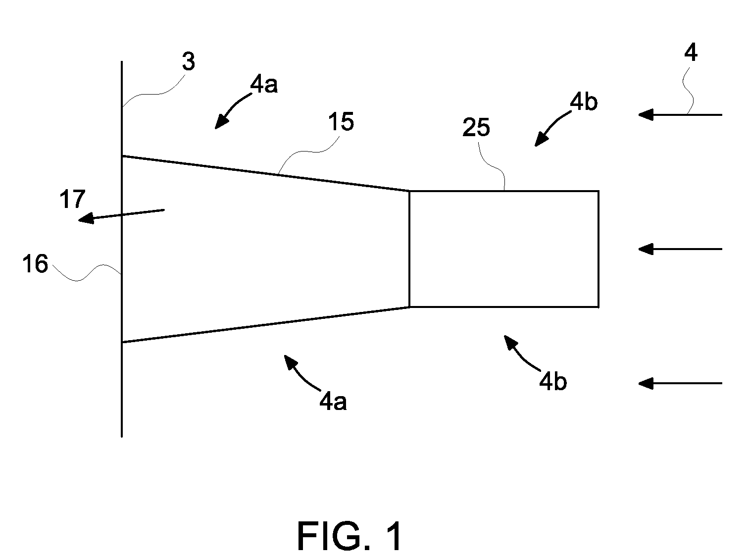
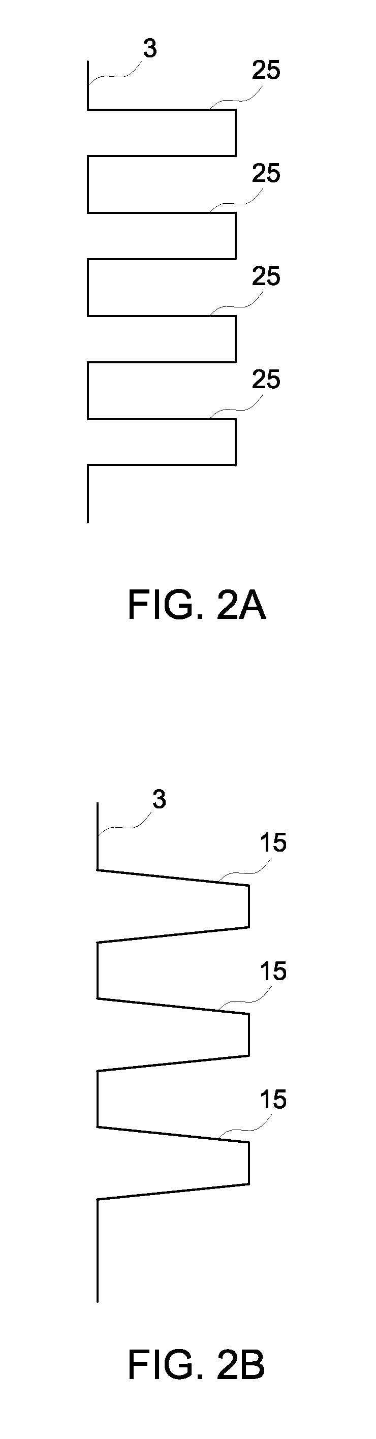
[0020]In the embodiment shown in FIG. 1, a first filter 15 has a first media and a second filter 25 has a second media. The first filter is a cone and the second filter is a cylinder. Arrows 4 show the direction of incoming airflow. The cone filter element 15 is connected to a tubesheet 3, which holds the fi...


PUM

PropertyMeasurementUnit
diameteraaaaaaaaaa
thicknessaaaaaaaaaa
RHaaaaaaaaaa

Abstract

A filtration system comprising at least one filter element, at least a first and a second filter media that are different to one another and are arranged in a parallel relationship, wherein fluid flow through the filtration system comprises a first fluid flow portion that flows through the first media and a second fluid flow portion that flows through the second media.

Description

BACKGROUND OF THE INVENTION[0001]1. Field of the Invention[0002]The field of the invention relates to filtration systems. In particular, the field of the invention relates to systems suitable for use in gas turbines for filtering inlet air to remove contaminants therefrom, across a variety of conditions.[0003]2. Description of Related Art[0004]Filter systems for gas turbine inlet air are known. Power generation equipment such as gas turbine engines use a large supply of intake air to enable combustion. To maintain suitable performance and reliability of the turbine the intake air is filtered to remove unwanted dust, moisture and other contaminants. Filters are generally subject to accumulation of particulates on and in the filter media over time, which adversely increases resistance to flow through the filters. Often, back-pulsing of air is used to clean the filters intermittently.[0005]Various filter media are known for filtering inlet air and they are generally tailored to optimis...

Claims


Application Information

Patent Timeline
Patent Type & Authority Patents(United States)
IPC IPC(8): B01D46/00B01D39/16B01D39/18B01D39/20B01D46/02B01D46/54
CPCB01D46/002B01D46/0021B01D39/1623B01D39/18B01D39/2017B01D46/0068B01D46/023B01D46/546B01D2239/025B01D2239/064B01D2239/1291B01D2267/40B01D2279/60B01D46/58B01D46/71B01D36/02B01D39/00B01D46/56F02C7/05F02C7/04B01D39/14B01D46/60
Inventor HINER, STEVE DAVIDRICHARDSON, PAULBRYANT, PAUL
Owner PARKER INTANGIBLES LLC
Why Eureka
Eureka Blog
Learn More