
Continuous pitch wind musical instrument

a musical instrument and continuous pitch technology, applied in the direction of wind musical instruments, instruments, musical instruments, etc., can solve the problems of inability to finely control the dynamic control of piston-type arrangements, inability to provide the required dynamic performance and control, and inability to achieve fine dynamic control

Active Publication Date: 2014-09-02
SHANKAR SANKARASUBRAHMANI UDAY
View PDF18 Cites 2 Cited by
  • Summary
  • Abstract
  • Description
  • Claims
  • Application Information

AI Technical Summary

Benefits of technology

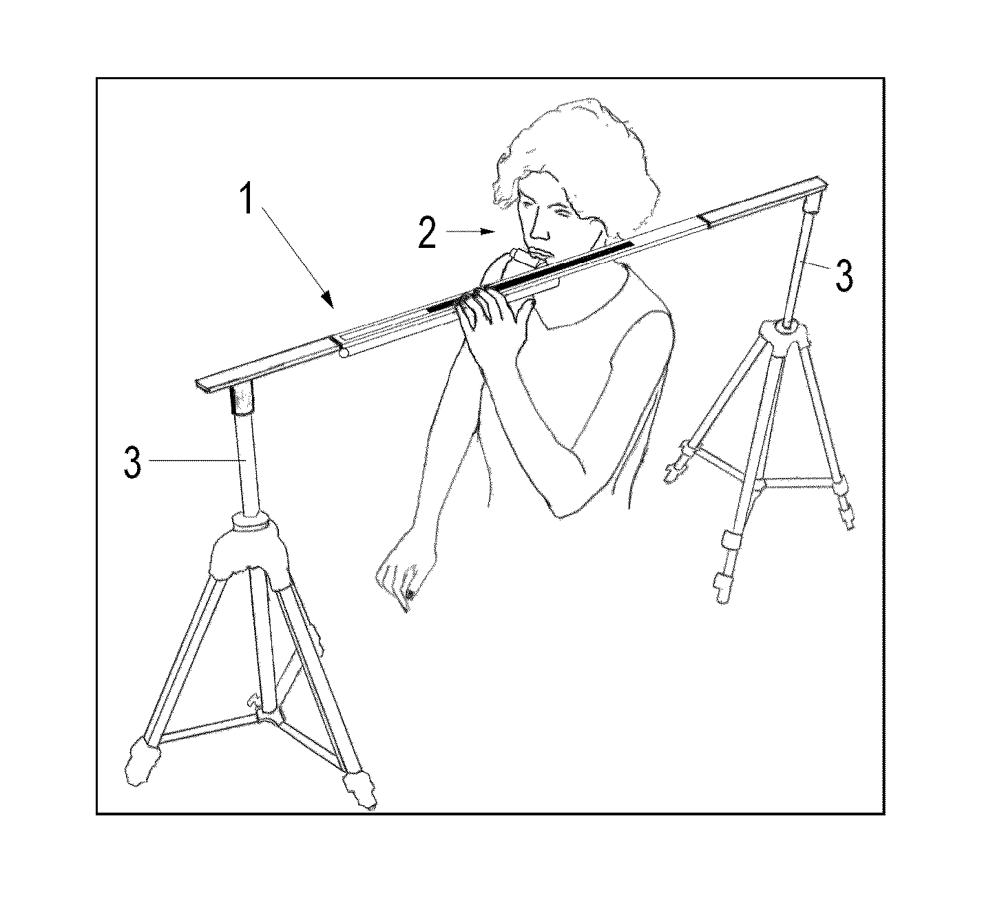
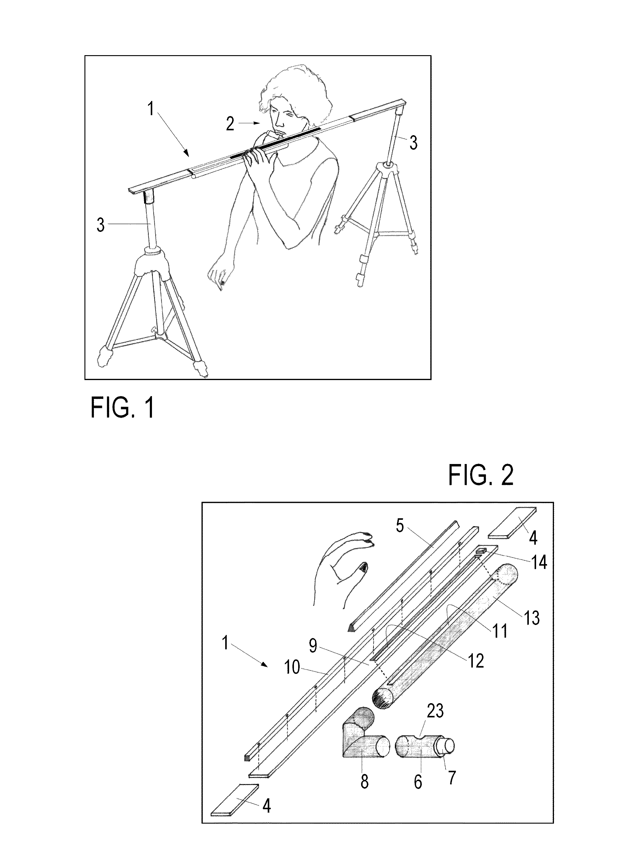
The present invention is a slide flute type of musical instrument that includes a resonating pipe and a rigid rod that slides along a length of the pipe and seals it to create an air seal. This instrument allows the player to create a resonant column of air in the pipe, which results in a pitch for the musical sound that depends on how far the rigid rod closes the first slot. The invention has technical advantages and provides a unique method for creating music.

Problems solved by technology

However, during the actual playing of such an instrument by virtue of moving the piston up and down the pipe, the closed pipe causes conflicting air flow patterns and pressure variations at the mouthpiece, which provides the only inlet as well as outlet for the enclosed air, leading to unintended and random overtone generation and other pitch variations.
Hence the sound produced by this instrument is often a medley of tones and pitches, quite unsuitable to play serious music and, hence, it is classified as a toy.
Quite apart from these limitations, the inherently sluggish movement of a piston type of arrangement does not lend itself to fine dynamic control.
The instrument disclosed this patent, while providing a practical viable flute design, is inadequate in providing the required dynamic performance and control as well as air seal.
As a result, sliding or continuous pitch flutes of this kind neither consistently produce the desired pitch nor allow for the desired fine dynamic control and hence are musically unviable.
This rotational design is not considered to practically yield the desired control or sound quality needed in the art.

Method used


Image

  • Continuous pitch wind musical instrument
  • Continuous pitch wind musical instrument
  • Continuous pitch wind musical instrument

Examples


Embodiment Construction

[0025]As used herein, the singular form of “a”, “an”, and “the” include plural references unless the context clearly dictates otherwise. As used herein, the statement that two or more parts or components are “coupled” shall mean that the parts are joined or operate together either directly or indirectly, i.e., through one or more intermediate parts or components, so long as a link occurs. As used herein, “directly coupled” means that two elements are directly in contact with each other. As used herein, “fixedly coupled” or “fixed” means that two components are coupled so as to move as one while maintaining a constant orientation relative to each other.

[0026]As used herein, the word “unitary” means a component is created as a single piece or unit. That is, a component that includes pieces that are created separately and then coupled together as a unit is not a “unitary” component or body. As employed herein, the statement that two or more parts or components “engage” one another shal...


PUM


Abstract

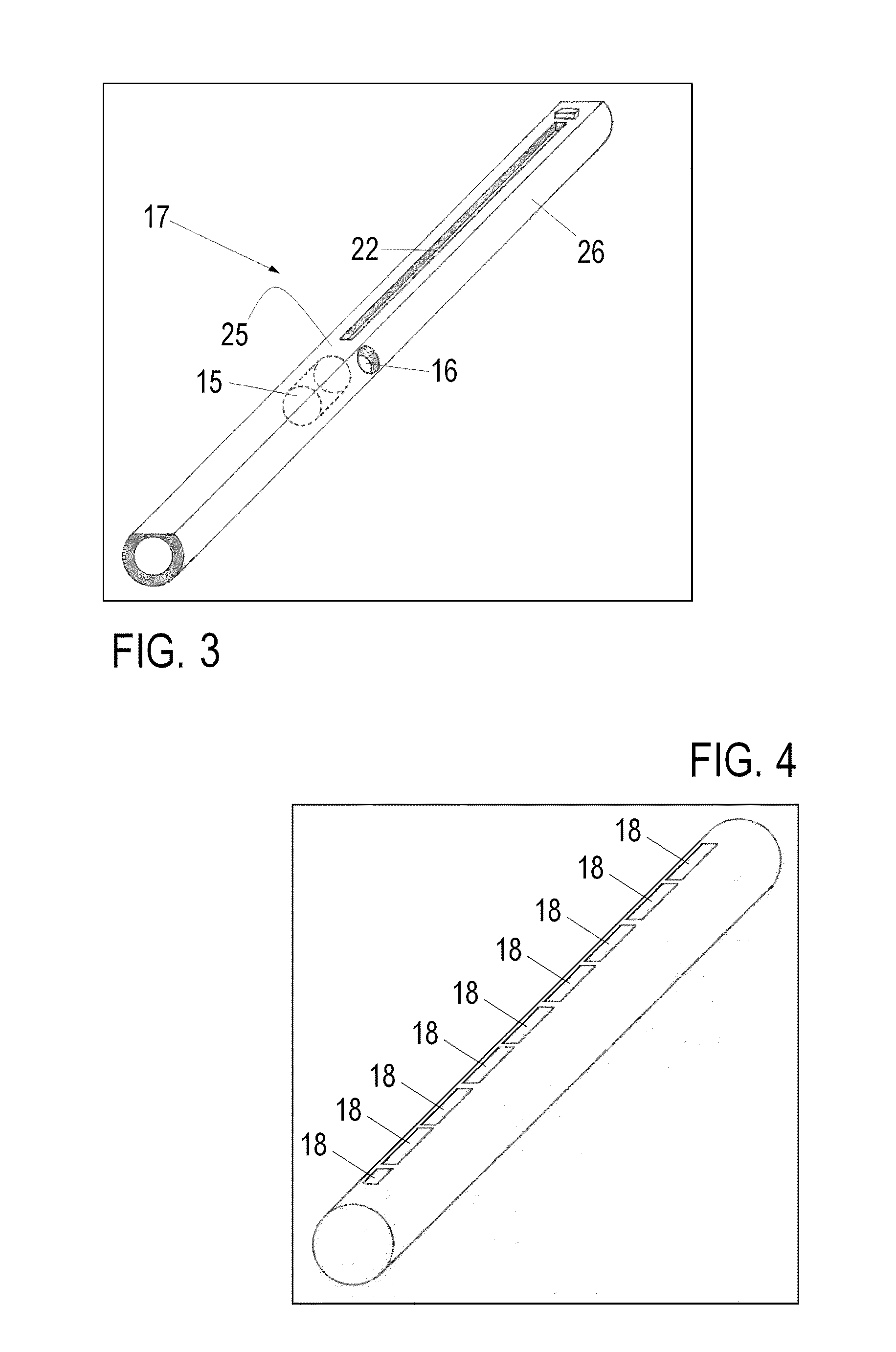
A musical instrument includes a resonating pipe having a first slot defined along a length of a longitudinal axis of the resonating pipe and a sliding rod that slides along a length of the first slot and closes the first slot such that the sliding rod selectively covers and provides an air seal to the first slot, such that a pitch of sound produced varies according to a length of closure of the first slot. A mouthpiece is coupled to the resonating pipe to enable the player to create a resonating column of air in the resonating pipe and control the pitch of the instrument by controlling the coverage of the sliding rod over the first slot.

Description

RELATED APPLICATIONS[0001]This application claims the benefit of International Patent application serial number PCT / IN2011 / 000605 filed Sep. 5, 2011 entitled “A Continuous Pitch Wind Musical Instrument” which published on Mar. 15, 2012, as WO 2012 / 032539 which publication is incorporated herein by reference. International Patent application serial number PCT / IN2011 / 000605 claims the benefit of Indian Application serial number 2587 / CHE / 2010 filed Sep. 6, 2010.BACKGROUND OF THE INVENTION[0002]1. Field of the invention[0003]The present invention pertains to a slide flute type of musical instrument, and, in particular, the present invention pertains to such an instrument with a wide octave range and fine control of the dynamic characteristics.[0004]2. Background Information[0005]Musical wind instruments fall into two major categories, namely open pipes and closed pipes. Open pipe musical instruments are resonant columns of air enclosed in a pipe with openings at both ends. Closed pipe i...

Claims


Application Information

Patent Timeline
Patent Type & Authority Patents(United States)
IPC IPC(8): G10D7/00G10D7/02
CPCG10D7/026G10D7/00
Inventor SHANKAR, SANKARASUBRAHMANI, UDAY
Owner SHANKAR SANKARASUBRAHMANI UDAY
Learn More