Breast pump

a technology of a pump and a hose, which is applied in the direction of suction devices, suction drainage systems, intravenous devices, etc., can solve the problems of general negative pressure generation and unhygienic situations

Active Publication Date: 2014-09-09
KONINK PHILIPS ELECTRONICS NV
View PDF11 Cites 42 Cited by
  • Summary
  • Abstract
  • Description
  • Claims
  • Application Information

AI Technical Summary

Benefits of technology

[0010]Therefore, it is an object of the invention to provide a breast pump which substantially alleviates or overcomes the problems mentioned above.

Problems solved by technology

However, a problem with the above described breast pump arrangement is that a negative pressure is generally generated at the breast to encourage milk expression by the pump unit producing a negative pressure below the atmospheric pressure.
This can lead to unhygienic situations because pumping mechanisms are difficult or impossible to clean by a user.
However, such an operation requires generation of a positive pressure in the insert and so a separate pump is required to generate such a pressure profile.

Method used


Image

  • Breast pump
  • Breast pump
  • Breast pump

Examples


first embodiment

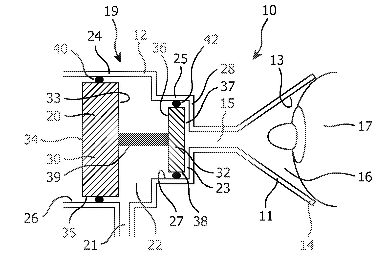
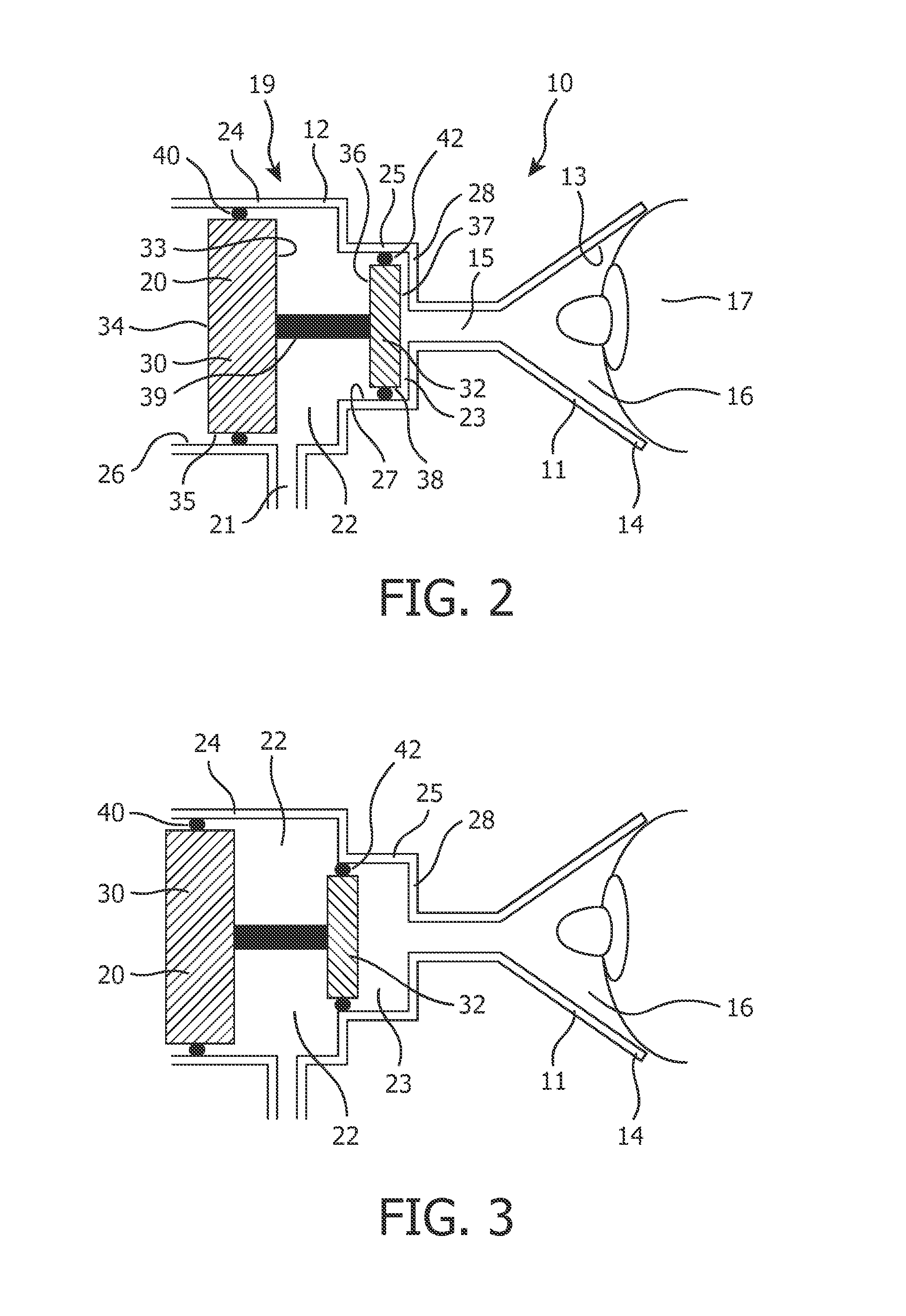
[0036]Operation of a breast pump will now be described with reference to FIGS. 2 and 3. A user inserts a breast 17 into the breast receiving recess 16 formed by the funnel 11 and locates the breast 17 against the inner surface 13 of the funnel 11 to form an air-tight seal. The actuator 20 is initially disposed in the compartment 19 in a neutral position, as shown in FIG. 2, with the second piston element 32 of the actuator 20 located proximate to the end face 28 of the compartment second section 25. The first and second pressure chambers are initially at an atmospheric pressure.

[0037]The user then operates the pump unit (not shown) to generate a positive pressure differential in the first pressure chamber 22. The pump unit (not shown) is a positive pressure pump unit and is fluidly connected to the first pressure chamber 22 by the inlet 21. Therefore, when the pump unit (not shown) is operated, the air pressure in the first pressure chamber increases and is sealed by the o-rings 40,...

second embodiment

[0044]a breast pump has an insert 50 disposed in the mouth 13 of the funnel 11. The insert 50 has a circle symmetric flexible, deformable wall 52 extending around an inner portion of the mouth 13 of the funnel 11 from an outer end 53 to proximate, or into, the throat 15 of the funnel 11. An inner face of the wall 52 forms the inner surface 13 of the funnel 11 against which a user's breast locates, and a cavity 54 is defined between the wall 52 and a funnel wall 55. The wall 52 is deformable into the breast receiving recess 16 during use to apply a compressive force to the nipple and / or areola in an attempt to aid the expression of milk from the breast, as will be explained hereinafter.

[0045]A pressure conduit 56 fluidly connects the cavity 54 to the first pressure chamber 22 so that the pressure generated in the first pressure chamber 22 is generated in the cavity 54.

[0046]The actuator 20 comprises a first piston element 30 and a connecting member which in this embodiment forms a se...


PUM


Abstract

In a breast pump, milk expressed from a user's nipple may be drawn into the pumping mechanism used to create a vacuum. This can lead to unhygienic situations because pumping mechanisms are difficult or impossible to clean by a user. The present invention relates to a breast pump comprising first and second pressure chambers (22, 23) and an actuator (20) disposed to fluidly divide the two chambers (22, 23). The actuator (20) is movable to generate an inverse pressure differential in the second chamber (23) when a pressure differential is generated in the first pressure chamber (22), or a pressure differential is released from the first pressure chamber (22). Furthermore, the actuator (20) comprises a first piston element (30) and a second piston element (32), and wherein the first pressure chamber (22) is disposed between the first piston element (30) and the second piston element (32).

Description

FIELD OF THE INVENTION[0001]The present invention relates to a breast pump for extracting milk from a breast of a user.BACKGROUND OF THE INVENTION[0002]Breast pumps are well known devices for extracting milk from a breast of a user. A breast pump may be used if the baby or infant is not itself able to express milk from the breast, or if the mother is separated from the baby or infant, for example, if away from the baby at work. The use of a breast pump to express milk may also be used to stimulate and increase milk production in women with a low milk supply.[0003]Breast pumps make use of a vacuum to induce milk expression from a nursing mother's breast. The pumping action of the device draws the milk from the nipple to a collection vessel, and the pressure and / or frequency may generally be adjusted to the preferences of the mother.[0004]WO 2004 / 058330 discloses a manual breast pump comprising a breast cup, a pump housing with a piston and an activation mechanism in the form of a han...

Claims


Application Information

Patent Timeline
Patent Type & Authority Patents(United States)
IPC IPC(8): A61M1/06A61M1/00
CPCA61M1/06A61M1/0037A61M1/0068A61M1/75A61M1/81A61M1/0697
Inventor BOSMAN, FRANCISCUS JOZEFMULDER, BERNARDO ARNOLDUS
Owner KONINK PHILIPS ELECTRONICS NV
Why Eureka
Try Eureka