Illuminator having improved distance illumination

a technology of illumination and distance, applied in the direction of lighting protection devices, lighting heating/cooling arrangements, lighting applications, etc., can solve the problem of not being convenient to illuminate, and achieve the effect of limiting glar

Inactive Publication Date: 2014-12-02
NUALIGHT
View PDF10 Cites 3 Cited by
  • Summary
  • Abstract
  • Description
  • Claims
  • Application Information

AI Technical Summary

Benefits of technology

[0013]In one embodiment, the diffuser is curved along the direction of the axis of the small cylinder lenses so as to minimise Fresnel losses.
[0023]In one embodiment, the baffles have a dimension normal to the substrate sufficient to act as visors to limit glare in the longitudinal direction.

Problems solved by technology

However there are situations in retail and other display situations where it is not convenient to illuminate from such short distances.

Method used


Image

  • Illuminator having improved distance illumination
  • Illuminator having improved distance illumination
  • Illuminator having improved distance illumination

Examples


Embodiment Construction

Brief Description of the Drawings

[0034]The invention will be more clearly understood from the following description of some embodiments thereof, given by way of example only with reference to the accompanying drawings in which:

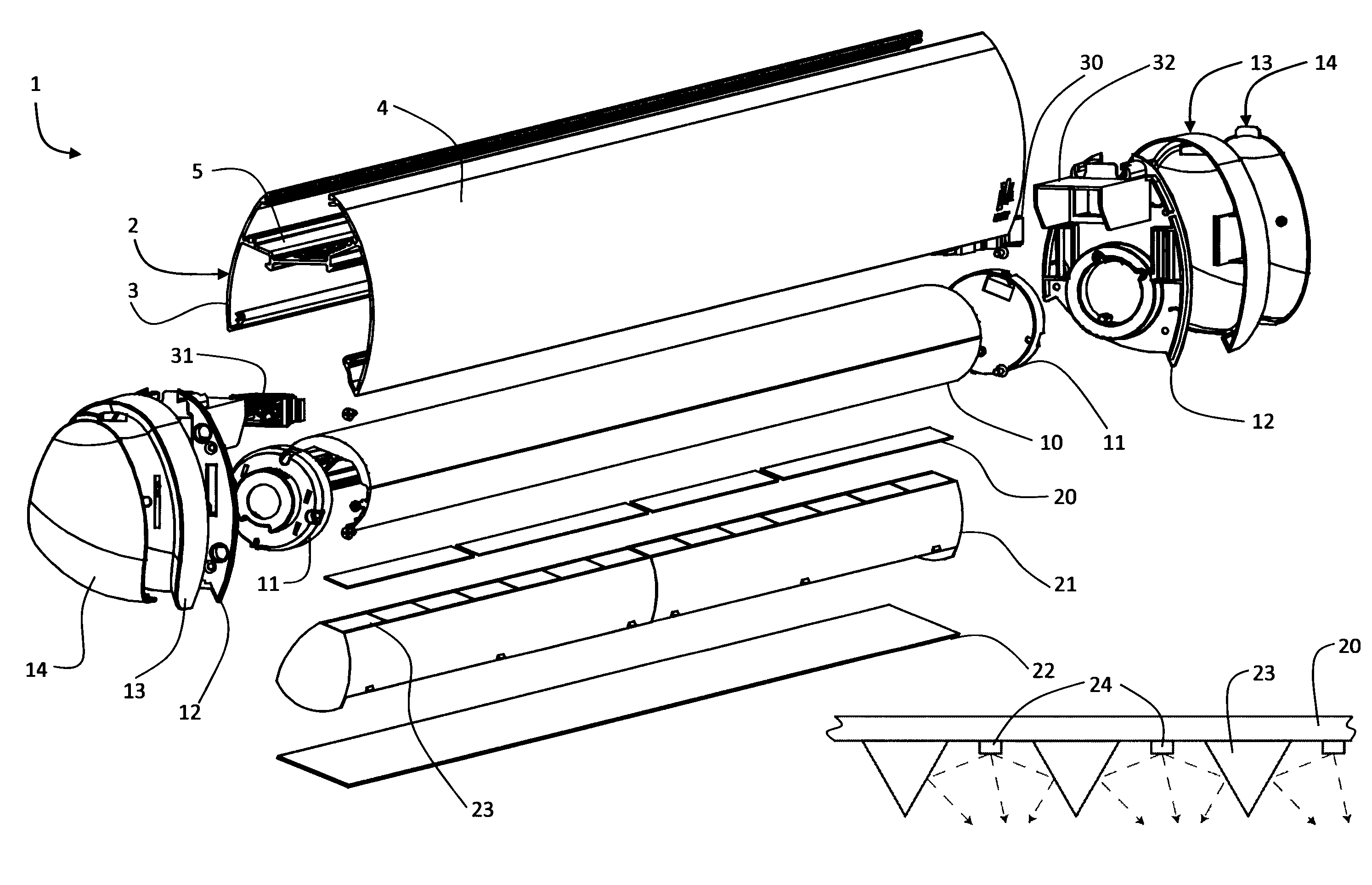
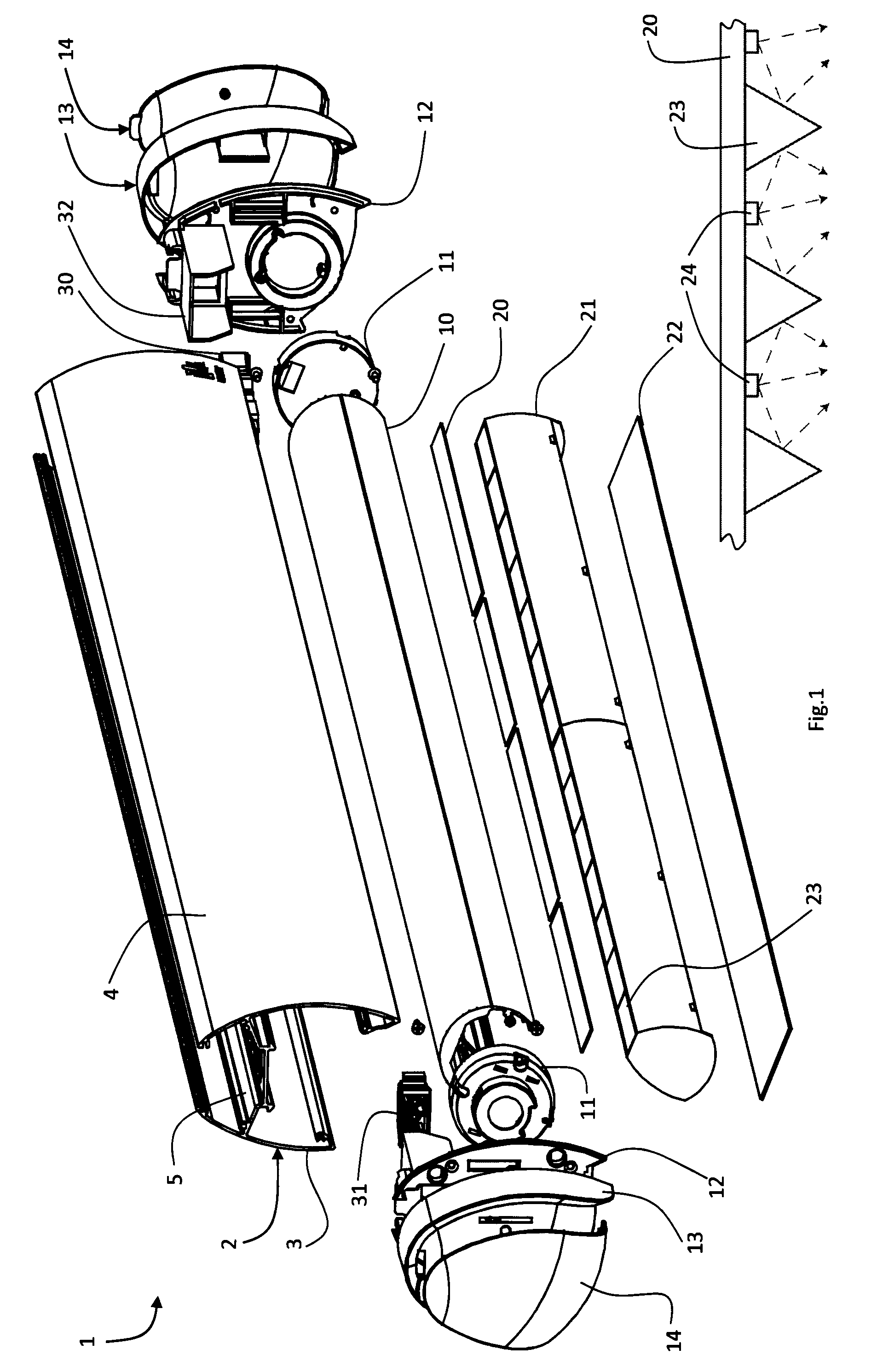
[0035]FIG. 1 is an exploded view of an illuminator of the invention;

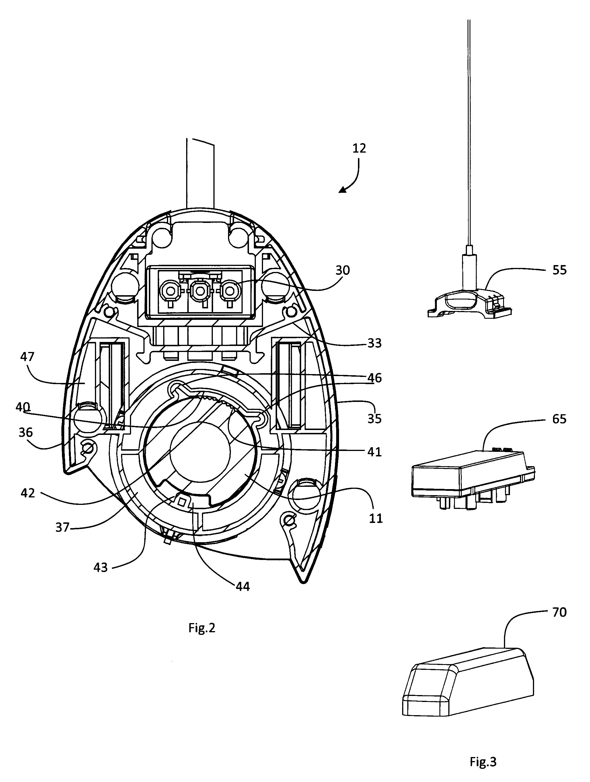
[0036]FIG. 2 is a front view of an end fixture of the illuminator;

[0037]FIG. 3 shows parts which fit in an upper compartment of the outer housing;

[0038]FIGS. 4(a) to 4(c) are cross-sectional views through the illuminator, showing three different illumination settings;

[0039]FIGS. 5 to 8 are diagrams illustrating use of the illuminator 1 in various retailing scenarios; and

[0040]FIG. 9 is a set of three diagrams showing versatility in illumination range.

DESCRIPTION OF THE EMBODIMENTS

[0041]Referring to FIGS. 1 to 4 an illuminator 1 of the invention comprises an outer housing 2 with unsymmetric side walls 3 and 4 interconnected by a top wall 5. The space above the wall 5 forms a compartment for a d...


PUM


Abstract

An illuminator (1) an elongate inner housing (10) having a substrate (20) on which there is a linear array of light emitting diodes (24), wherein the diodes have sufficient power for illuminating objects at a distance of at least 1.5 m. A drive circuit (30, 31) is mounted in an upper compartment of an outer housing (2) at least partly surrounding the inner housing (10). There is a diffuser (22) over the diodes. There is a pair of side reflectors extending substantially parallel to an axis of the illuminator, being side walls (26) of the inner housing. The inner housing (10) is coupled to the outer housing (2) in a modular manner so that it is interchangeable. There is a series of reflector baffles (23) extending from a plane of the diodes at intervals along the length of the inner housing. The baffles (23) have textured surfaces and have a dimension normal to the substrate sufficient to act as visors to limit glare in the longitudinal direction.

Description

[0001]This is a national stage of PCT / IE11 / 000051 filed Sep. 9, 2011 and published in English, which has a priority of Irish no. 2010 / 0568 filed Sep. 10, 2010, hereby incorporated by reference.INTRODUCTION[0002]The invention relates to LED Illuminators.[0003]Our prior PCT published patent specifications WO2006067777 and WO2008047335 describe illuminators for retail applications. They are suitable for illumination from a short distance, within or alongside a display cabinet.[0004]However there are situations in retail and other display situations where it is not convenient to illuminate from such short distances. An example is a set of open shelves for goods such as vegetables. Heretofore, the approach has been to use general blanket lighting fixtures typically by fluorescent light fittings.[0005]The invention is directed towards providing for improved distance illumination for such situations.SUMMARY OF THE INVENTION[0006]According to the invention, there is provided an illuminator ...

Claims


Application Information

Patent Timeline
Patent Type & Authority Patents(United States)
IPC IPC(8): A47F11/10F21S4/00F21Y101/02F21Y103/00F21V14/04F21V13/04F21V15/01F21W131/405F21V7/00F21V21/30F21V5/00
CPCF21V15/011F21V5/004F21Y2103/003F21Y2101/02F21V13/04F21V14/04F21W2131/405A47F11/10F21S4/008F21V7/005F21V21/30F21V7/0025F21V15/013F21V29/507F21S4/28F21Y2103/10F21Y2115/10
Inventor LINEHAN, DANIELHENNESSY, TOMASCRONIN, ANDREWDEBARBOUILLE, RICHARD PIERRE JOSEPH
Owner NUALIGHT
Why Eureka
Try Eureka