Gas-discharge lamp for a vehicle headlamp

a technology for gas-discharge lamps and headlamps, which is applied in the direction of fixed installation, transportation and packaging, lighting and heating equipment, etc., can solve the problems of reducing the beam length and width by up to 50%, the possibility of using r-type lamps, and glare levels which are not acceptable, so as to facilitate the generation of clear cut-off lines and limit glare

Inactive Publication Date: 2017-11-30
KONINKLJIJKE PHILIPS NV
View PDF1 Cites 0 Cited by
  • Summary
  • Abstract
  • Description
  • Claims
  • Application Information

AI Technical Summary

Benefits of technology

[0012]An advantage of the gas-discharge lamp according to the invention is that it can be used in both R-type and S-type headlamps, i.e. in both reflector headlamps and projector headlamps without the need of the end used to adapt the HID bulb with respect to the type of his headlamp. Therefore, the driver of an automobile with projector headlamps could replace a defective D2S lamp by a lamp according to the invention. Equally, the driver of an automobile with reflector headlamps could replace a defective D4R lamp by a lamp according to the invention. The HID bulb according to the invention presents a considerable simplification to manufacturers, retailers and consumers regarding the aftermarket business. Instead of having to manufacture, distribute and choose from a multitude of different Xenon HID bulb types, a single Xenon HID bulb type can suffice. This presents a significant cost saving to the manufacturer and also to the distributors, and the customer can more easily identify a suitable HID bulb to replace a defective one.
[0018]In a reflector lamp or projector lamp, the lamp optics serve to collect as much light as possible, shape it to achieve a desired front beam shape, and cast the front beam outwards from the headlamp. The bright / dark cut-off line is a critical characteristic of a front beam. Very little light—preferably none at all—should stray above the cut-off line, in order to limit glare for oncoming traffic. Therefore, in a further preferred embodiment of the invention, the lamp comprises two lateral stripes, one on each side of the vessel. This design facilitates generation of a clear cut-off line across the width of the front beam. Preferably, the two lateral stripes have essentially identical dimensions, and the radial position of both lateral stripes on the lamp (i.e. their positions relative to a horizontal plane through the center of the lamp) preferably corresponds to the radial position of lateral pinstripes on a standard R-type Xenon HID lamp.
[0019]Since the front beam is essentially “composed” of many images of the discharge arc cast outward from the lamp (in the case of a reflector lamp), the lateral stripe is preferably slightly longer than a region corresponding to the length of the electrode gap. This helps to ensure a sharp cut-off line, even if the electrode tip should burn back over time, with the result that the electrode shortens and the gap lengthens. Additionally, axial position tolerances of both electrode tips on the order of + / −0.2 mm should be taken into account. The longitudinal stripe extends by a distance of at most 2.0 mm, preferably 1.5 mm, and most preferably at most 1.0 mm, in the direction of an outer end region of the lamp, since the light emitted into the corresponding solid angle of the Xenon HID lamp is directed into area of the glare zone area close to the central position of the cut-off line, corresponding to a region in the line of sight of an oncoming driver.
[0022]In a further embodiment of the lamp according to the invention, an additional narrow circumferential strip is applied at the inner end of the lamp, i.e. at the end of the lamp closest to the housing. The edge of the circumferential strip that is closest to the discharge arc preferably corresponds to the edge of the circumferential strip as specified for an R-type Xenon HID lamp. The width of the circumferential strip is preferably at most 4.0 mm, most preferably at most 2.0 mm. The circumferential strip is separate from the lateral strip, so that the relevant edges of the circumferential and lateral strips are separated by at least 1.0 mm. The circumferential strip significantly reduces the glare well above the bright / dark cut-off line. This region mainly corresponds to glare perceived by oncoming traffic at a distance of 20-100 m in front of the vehicle. Even though this embodiment makes use of a circumferential strip in addition to the lateral strip, this lamp can still be used in an S-type headlamp since the circumferential pinstripe is far behind the first electrode and thus has only a very weak impact on the light distribution of an S-type headlamp beam pattern. On the other hand, the additional narrow circumferential pinstripe slightly increases the temperature of the inner discharge vessel and thus improves the efficiency of the HID bulb, resulting in a brighter light output. The improved efficiency can therefore compensate for any light losses due to the “shadowing” effect of the pinstripes.

Problems solved by technology

Because the known HID lamps are specifically designed as either R-type or S-type, it is not possible to use an R-type lamp in an headlamp designed for use with an S-type lamp, since an acceptable beam pattern cannot be achieved if an R-type HID lamp is inserted into an S-type headlamp, and vice versa.
For example, an S-type bulb in an R-type headlamp would result in glare levels which are not acceptable.
On the other hand, using an R-type bulb in an S-type headlamp would reduce the beam length and width by up to 50%, which is clearly also not acceptable.
The driver of an automobile cannot be assumed to know which type of lamp is allowed for the vehicle headlamp, and it may be that a driver is not sure which choice of bulb is correct.
Choosing the correct bulb is also difficult in the face of great variety of bulbs being manufactured by the various suppliers.
This makes the overall situation complicated and confusing from the point of view of manufacturer, retailer and consumer.
Due to the sophisticated mounting construction, the required precision, the high temperature load and the large size of the metal frame, such solutions are very expensive to manufacture.
However, in this alternative solution, the metal shield cannot block unwanted light as effectively as pinstripes applied directly onto the lamp, and mounting or construction errors detract further from the quality of the resulting front beam.

Method used


Image

  • Gas-discharge lamp for a vehicle headlamp
  • Gas-discharge lamp for a vehicle headlamp
  • Gas-discharge lamp for a vehicle headlamp

Examples


Embodiment Construction

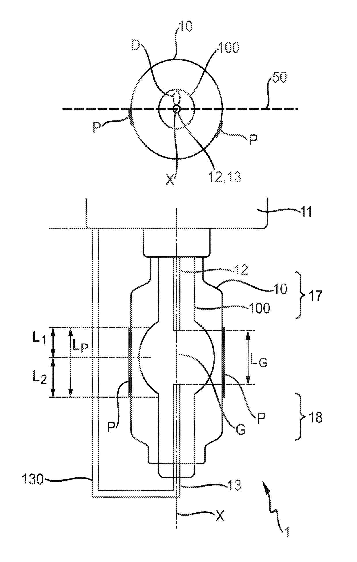
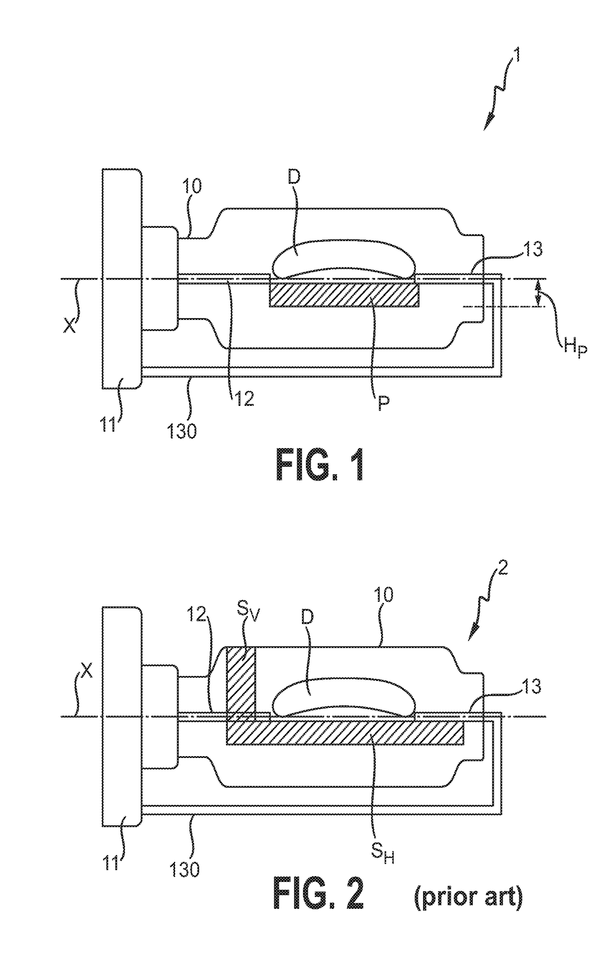
[0034]FIG. 1 shows a HID lamp 1 according to an embodiment of the invention. The lamp 1 comprises an outer vessel 10 or envelope 10 enclosing an inner vessel 100 or burner 100. Two electrodes 12, 13 extend into the burner 100 and their tips face each other across a narrow gap G. A return lead 130 provides an electrical connection between the outer electrode 13 and a base 11 or ballast housing 11 of the lamp 1, so that both electrodes 12, 13 can be electrically connected to a ballast (not shown). The geometrical construction details of this lamp 1 correspond essentially to those of a standard D2R lamp. When the lamp 1 is ignited, a discharge arc D is established between the electrode tips. The discharge arc D will have a curved bow shape extending above a longitudinal axis X extending through the center of the lamp 1. The diagram shows a lateral stripe P applied to an outer surface of the envelope 10. The stripe P is arranged such that it does not extend above the level of the longit...


PUM


Abstract

The invention describes a gas-discharge lamp comprising an inner vessel enclosing a pair of electrodes separated by a gap; and an outer vessel enclosing the inner vessel; and wherein the lamp comprises a lateral stripe arranged on the surface of a vessel such that the lateral stripe lies below a horizontal plane through a longitudinal axis through the center of the lamp, and wherein the lateral stripe extends essentially only over a region corresponding to the gap between the electrodes.

Description

FIELD OF THE INVENTION[0001]The invention describes a gas discharge lamp.BACKGROUND OF THE INVENTION[0002]To ensure traffic safety and to facilitate trade, design and construction aspects, vehicle headlamps are specified by internationally recognized UN / ECE regulations. Generally, it is of critical importance that the front beam profile satisfies strict requirements, for example requirements relating to the shape of a bright / dark cut-off line, the maximum light intensity that is allowed above the bright / dark cut-off line, etc. Other characteristics such as color temperature, lamp driver characteristics, lamp dimensions, etc. are also governed by applicable regulations. High-intensity discharge lamps (HID lamps) such as Xenon HID lamps are widely used in automotive headlamp applications, since they can provide an intensely bright light.[0003]There are basically two different types of vehicle headlamps for use with a HID bulb, namely a projector headlamp and a reflector headlamp. In a...

Claims


Application Information

Patent Timeline
Patent Type & Authority Applications(United States)
IPC IPC(8): H01J61/02F21S8/10H01J61/35H01J61/54
CPCH01J61/025H01J61/35H01J61/54F21S48/145F21S48/1186H01J61/34F21S41/172F21S41/43
Inventor KUEPPER, LUKASDOHMEN, HANS-ALOLENZEN, THORSTEN ERICH
Owner KONINKLJIJKE PHILIPS NV
Why Eureka
Try Eureka