Automatic injection mechanism with frontal buttress

a technology of frontal buttress and injection mechanism, which is applied in the direction of intravenous devices, medical syringes, injection needles, etc., can solve the problems of increasing the risk of fracture, high degree of dimensional variability, and impact load on fragile syringe flanges

Active Publication Date: 2014-12-02
WEST PHARM SERVICES INC
View PDF31 Cites 30 Cited by
  • Summary
  • Abstract
  • Description
  • Claims
  • Application Information

AI Technical Summary

Problems solved by technology

Glass syringes, and more particularly cut flange syringes, represent a number of challenges in autoinjector applications because they are fragile and easily broken components with a relatively high degree of dimensional variability.
In addition, due to the abrupt deceleration of the syringe / carrier assembly at the end of needle insertion, impact loads are imposed on the fragile syringe flanges.
The bending moment increases the stress applied to the fragile flange increasing the risk of fracture.
Such variability in residual medicament volume translates into significant monetary waste due to the relatively high cost of the drugs used to manufacture the medicaments.
Thus, conventional autoinjectors are deficient in that they cannot accommodate conventional pre-filled glass syringes (i.e., staked-needed syringes) to effectively address the issues associated with fragile and irregular components while assuring accurate needle placement and precise dose delivery due to the dimensional variability of glass syringe manufacturing.
However, the use of such handles to disengage the RNS creates an annular void or open end about the distal end of the autoinjector.

Method used


Image

  • Automatic injection mechanism with frontal buttress
  • Automatic injection mechanism with frontal buttress
  • Automatic injection mechanism with frontal buttress

Examples


Embodiment Construction

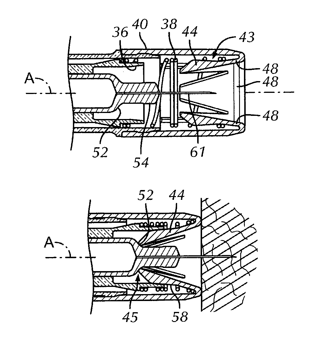
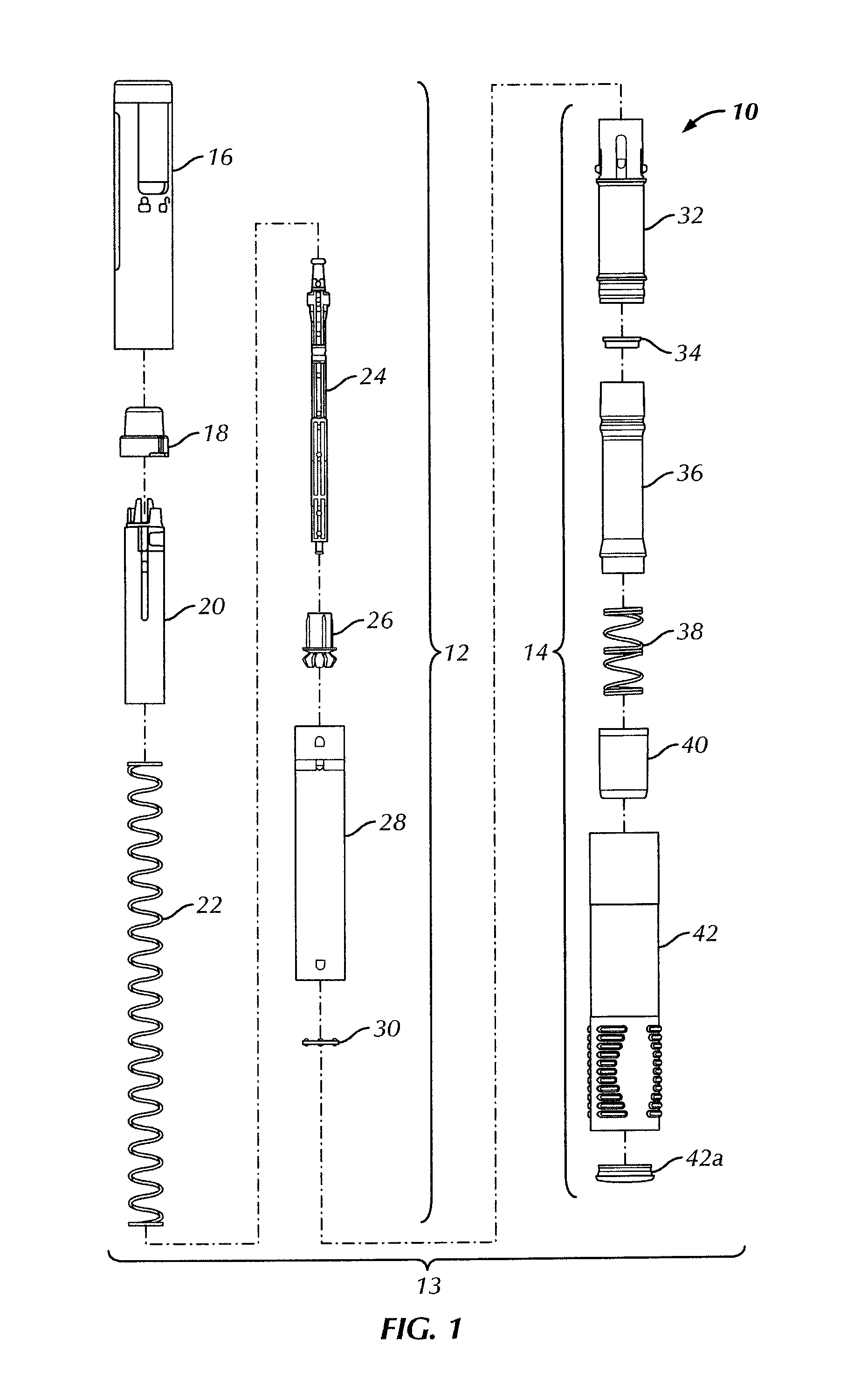
[0033]In a preferred embodiment, the present invention provides for an automatic injection device that includes an automatically deployable buttress upon which a syringe can be registered. As shown in FIGS. 1, 3, 6 and 7, the autoinjector 10 includes a housing 13 generally formed by various components of an injection assembly (or power pack subassembly) 12 and a window tube subassembly 14, such as an inner housing 20, a mid housing 28, a window tube 32 and a nose 40. While the present embodiment preferably includes an injection assembly 12, it is within the intent and scope of the present invention, that any injection assembly capable of automatically deploying or of causing a syringe to be automatically injected, can be used. For example, exemplary automatic injection devices applicable to the present invention include those disclosed in U.S. Pat. No. 6,387,078 to Gillespie, III, the disclosure of which is hereby incorporated by reference in its entirety. In general, the autoinject...


PUM


Abstract

The present invention provides for an autoinjector that registers off a distal end of a syringe to provide for a more accurate needle insertion depth. The autoinjector employs an automatically deployable frontal buttress for registration of the distal end or shoulder of the syringe.

Description

CROSS-REFERENCE TO RELATED APPLICATION[0001]This application is a Section 371 of International Application No. PCT / US2009 / 047483, filed Jun. 16, 2009, which is not yet published, and this application claims the benefit of priority pursuant to 35 U.S.C. §119(e) of U.S. Provisional Patent Application No. 61 / 074,253, filed Jun. 20, 2008, the disclosure of which is hereby incorporated by reference in its entirety.BACKGROUND OF THE INVENTION[0002]The present invention relates to automatic injection devices (“autoinjectors”). In particular, the present invention relates to an autoinjector having an automatically deployable frontal buttress.[0003]Autoinjector mechanisms have commercially been developed to substitute an automated mechanism for the manual action of inserting a hypodermic needle into a recipient's flesh and forcing the liquid medicament out of the syringe, through the hypodermic needle and into the recipient. In some cases, the automated mechanisms are designed to utilize com...

Claims


Application Information

Patent Timeline
Patent Type & Authority Patents(United States)
IPC IPC(8): A61M5/32A61M5/30A61M5/46A61M5/31A61M5/20
CPCA61M5/3204A61M2005/3142A61M2005/206A61M5/46A61M5/2033A61M2005/2073A61M5/3202
Inventor CROW, DOUG OWEN
Owner WEST PHARM SERVICES INC
Why Eureka
Try Eureka