
Device and method for depalletizing stacked bundles

a technology for stacked bundles and devices, applied in the direction of lifting devices, de-stacking articles, apparel, etc., can solve the problems of complete operation failure of a known depalletizing tool, depalletizing process can be sensitively disrupted or, respectively, hindered, etc., and achieves simple positioning of the hold-down clamp, high operating safety, and high contact pressure force

Inactive Publication Date: 2014-12-23
KUKA ROBOTER
View PDF23 Cites 5 Cited by
  • Summary
  • Abstract
  • Description
  • Claims
  • Application Information

AI Technical Summary

Benefits of technology

The solution enables reliable and safe lifting of containers in various packaging forms, improving coordination between lifting elements and preventing loose objects from interfering with the depalletizing process, thus enhancing operational safety and efficiency.

Problems solved by technology

It is disadvantageous that only one single-sided action on the goods is possible, such that a brace is necessary and—since the goods are tilted upon lifting and the distance between brace and lifting roller increases—either the brace or the lifting roller must be elastically arranged, wherein a difficult coordination is to be conducted between elastic yielding force and friction coefficient of the roller.
Depalletizing tools known from the prior art also exhibit the disadvantage that the depalletizing process can be sensitively disrupted or, respectively, hindered by a presence of loose objects arranged on the top of a container unit (for example coverings or cover layers in the most varied embodiments or materials).
For example, a sliding or canting of such objects during an unloading process can lead to a complete operational failure of a of a known depalletizing tool, with a significant time and repair cost associated therewith.

Method used


Image

  • Device and method for depalletizing stacked bundles
  • Device and method for depalletizing stacked bundles
  • Device and method for depalletizing stacked bundles

Examples


Embodiment Construction

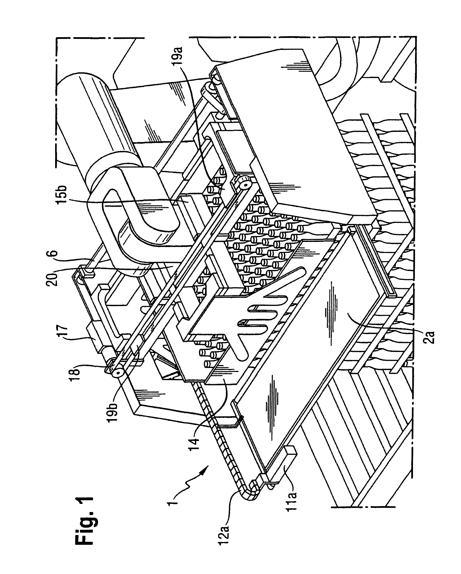
[0035]FIG. 1 is an overview representation in which a device according for depalletizing according to the invention is connected with a robot that encompasses the uppermost layer of a container stack located on a pallet in order to lift this from the remaining stack.

[0036]The device for depalletizing according to the invention is described in detail in the following using additional Figures.

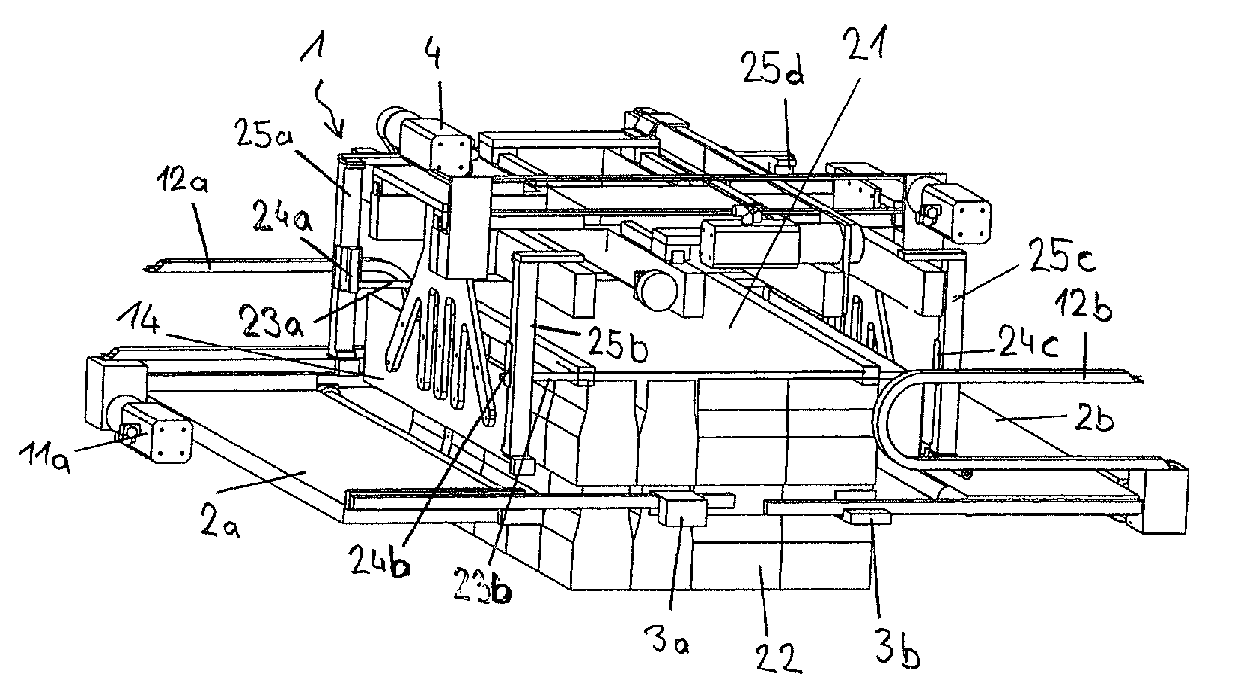
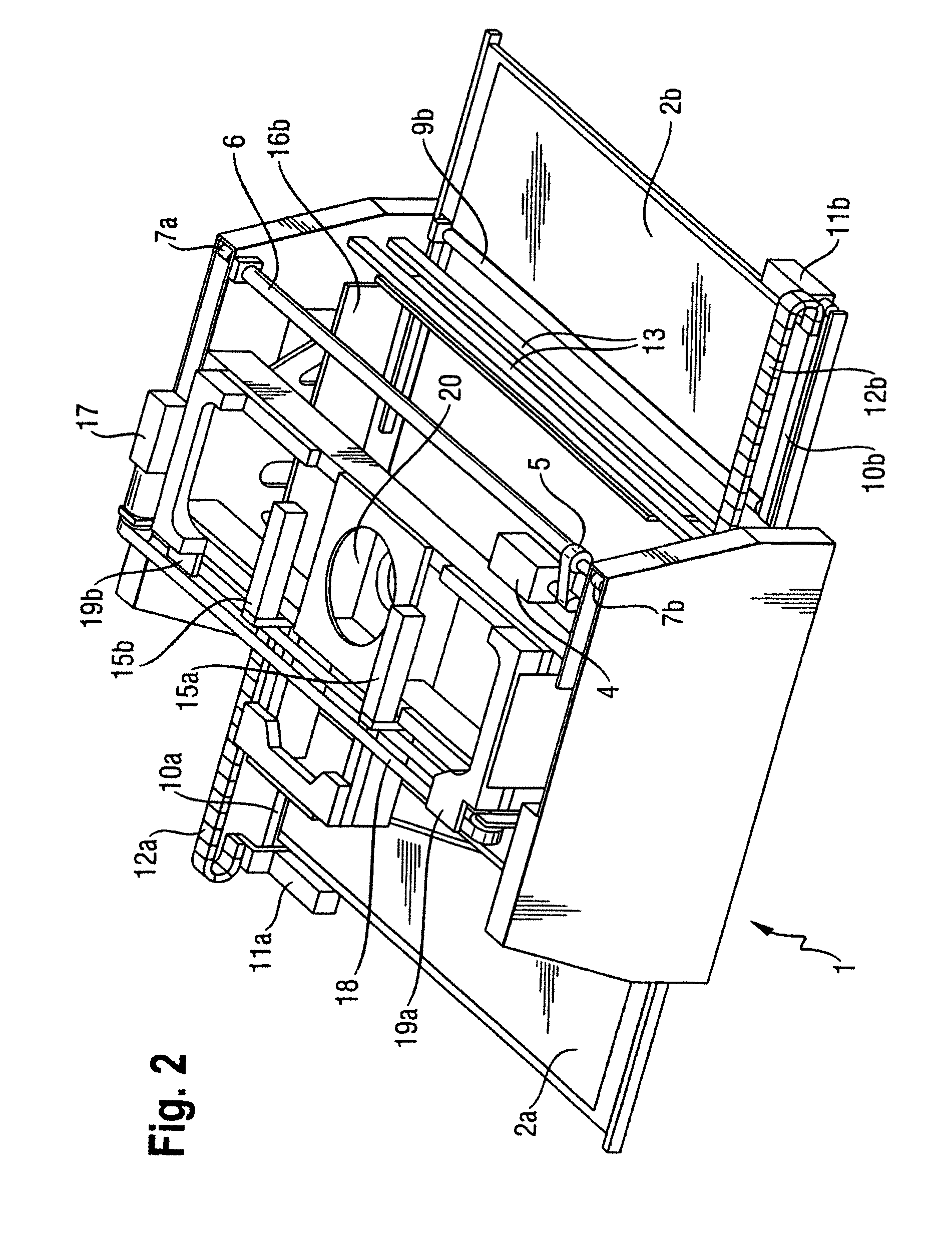
[0037]The depalletizing tool according to the invention possesses a base frame 1 on whose underside two support base parts 2a and 2b (here as support base halves) can be moved towards and away from one another by means of slide bearings 3a, 3b. For an automatic movement of the support base parts 2a and 2b, a common electrically drivable motor 4 is provided that drives (via a first synchronous belt 5) a distributor shaft 6 which drives a right drive belt 7a and a left drive belt 7b. The drive belts 7a and 7b are for their part connected with a carrier 8a and 8b that are in turn respectively connec...


PUM


Abstract

In a method and device for depalletizing stack containers, the stacked containers are supported by at least one support base, and the stacked containers on the support base are frictionally engaged and lifted on two opposite sides thereof.

Description

BACKGROUND OF THE INVENTION[0001]1. Field of the Invention[0002]The present invention concerns a method for depalletizing stacked containers, of the type wherein containers are lifted in a frictionally engaged manner and are underridden by at least one support base, as well as a device for depalletizing stacked containers, with at least one roller to lift the containers and with a support base.[0003]The invention in particular concerns the depalletizing of containers stacked on a pallet[0004]2. Description of the Prior Art[0005]Individual goods or connected goods containers are typically stacked in multiple layers on a palette and are arranged there for a transport. Given homogeneous palletizing, identical goods (such as beverage containers, for example) are stacked on the pallet. Given mixed palletizing, different goods or goods containers are arranged on a single palette. This is also called mixed commissioning. A wide-spread application is the arrangement of a mixed pallet of goo...

Claims


Application Information

Patent Timeline
Patent Type & Authority Patents(United States)
IPC IPC(8): B65G59/00B66C1/02B65G59/02A44B99/00B65G59/04
CPCB65G59/02B65G59/04B65G59/023Y10S414/12B66C1/0218Y10T24/2157
Inventor BAUMANN, MICHAELFELLNER, HERBERT
Owner KUKA ROBOTER
Learn More