
Head mounted display

a display and head technology, applied in the field of head mounted displays, can solve the problem that the display image becomes hardly identifiable, and achieve the effect of visualizing any display image easily

Inactive Publication Date: 2015-01-06
BROTHER KOGYO KK
View PDF17 Cites 4 Cited by
  • Summary
  • Abstract
  • Description
  • Claims
  • Application Information

AI Technical Summary

Benefits of technology

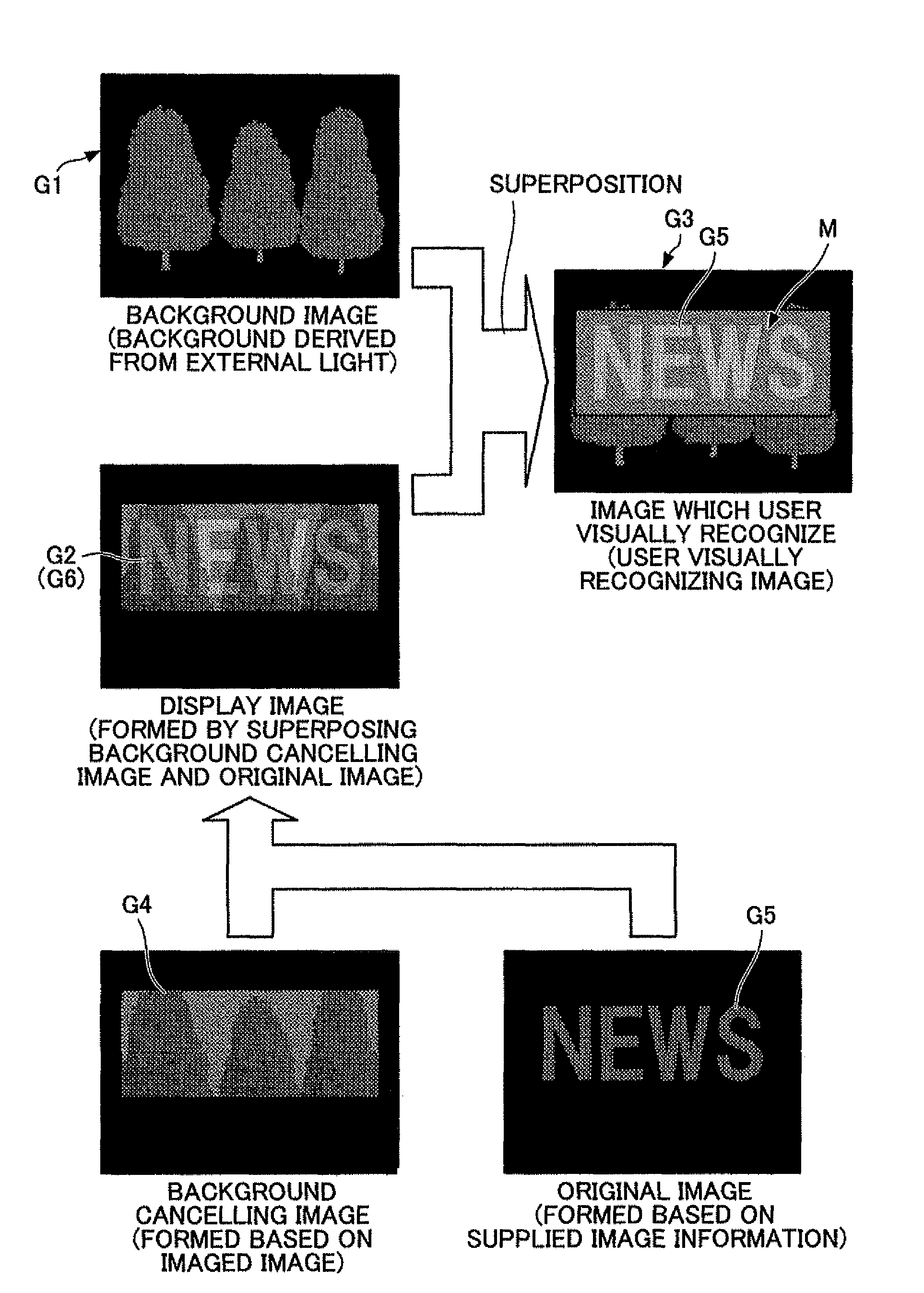
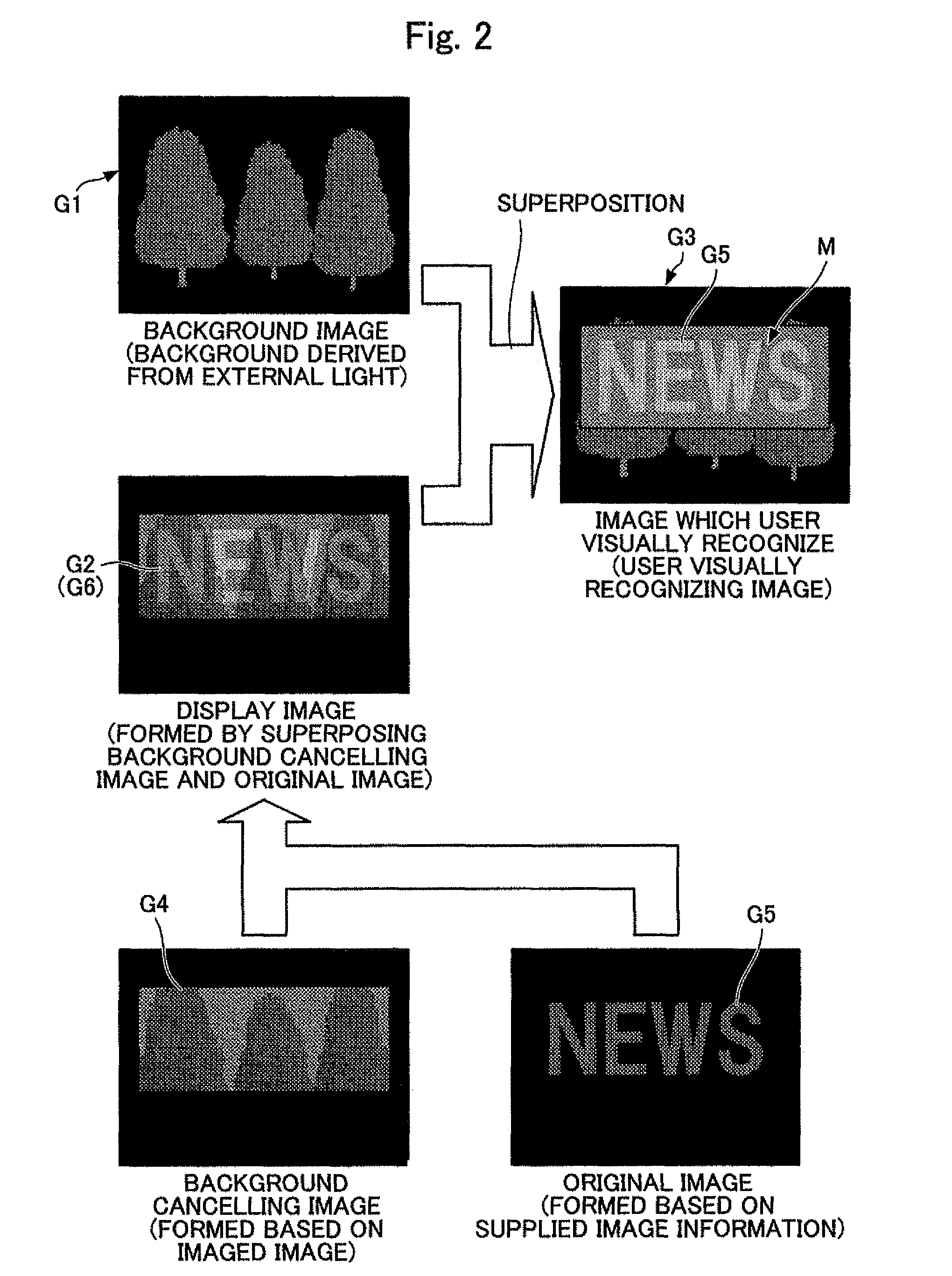
The present invention relates to a see-through-type head mounted display (HMD) which allows a user to easily recognize any display image without it becoming indistinguishable from the background image. The invention achieves this by using an image forming unit to create a background cancelling image that cancels out the background image when combined with the original image. The background cancelling image is generated by imaging a predetermined range of the image and aligning it with the original image. The display control unit then shows the combined image to the user. This invention addresses a common issue when wearing an HMD and allows for easier recognition of display images.

Problems solved by technology

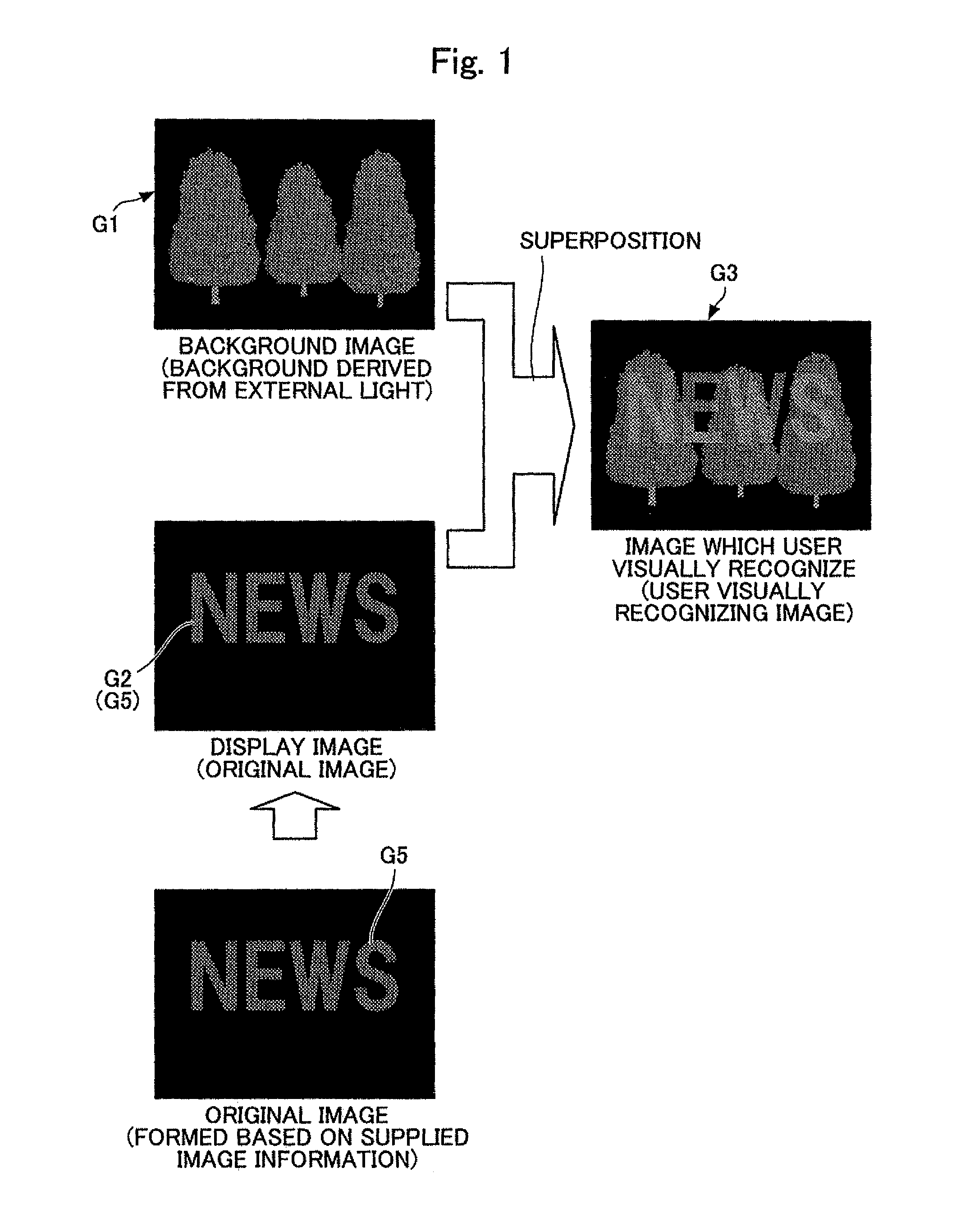
However, in the above-mentioned conventional see-through-type HMD, when a content of a display image is a fine image such as a character or a complicated pattern, an image having brightness near brightness of a background image or the like, the display image becomes indistinguishable from the background image so that the display image becomes hardly recognizable.

Method used


Image

  • Head mounted display
  • Head mounted display
  • Head mounted display

Examples


Embodiment Construction

[0033]An HMD according to this embodiment, in displaying an image to a user, forms a region where a part of or the whole external scenery is cancelled in the direction of line of sight of a user, and an image is displayed in this scenery-cancelled region. Accordingly, a user can visually recognize an image displayed by the HMD easily. Particularly, the visibility of an image having relatively a large number of edges such as a character and a pattern can be enhanced. In the explanation made hereinafter, the external scenery in the direction of line of sight of the user is referred to as “background image” and a region where a part of or the whole background image is cancelled is referred to as a mask region.

[0034]The HMD according to this embodiment is briefly explained in conjunction with drawings. In the explanation made hereinafter, “image” means, unless otherwise specified, “image” which a user visually recognizes, and may also mean image data or image signal. This “image” may be...


PUM


Abstract

An imaging unit images a predetermined range including at least a range where an image is displayed out of a field-of-view range of a user. An image forming unit forms a background canceling image which cancels a background image which is visually recognized by a user via an external light based on an imaged image imaged by the imaging unit. The image forming unit combines the background canceling image with the original image corresponding to original image information by aligning them in terms of display position and size. An image formed by combining the background canceling image with the original image is displayed on the display unit by a display control unit.

Description

CROSS-REFERENCE TO RELATED APPLICATIONS[0001]The present application is a Continuation-in-Part of the International Application PCT / JP2010 / 050836 filed on Jan. 22, 2010, which claims the benefits of Japanese Patent Application No. 2009-015661 filed on Jan. 27, 2009.BACKGROUND[0002]1. Field[0003]The present invention relates to a head mounted display (hereinafter referred to as HMD).[0004]2. Description of the Related Art[0005]Conventionally, there has been known a see-through-type HMD. This see-through-type HMD includes a display unit which projects an image light having intensity corresponding to image information thus allowing a user to visually recognize a display image which is a virtual image corresponding to the image light in front of an eye of the user while allowing an external light to pass therethrough (see JP-A-2006-165773, for example).[0006]Accordingly, the user who wears the see-through-type HMD on his head visually recognizes both a background image which is scenery ...

Claims


Application Information

Patent Timeline
Patent Type & Authority Patents(United States)
IPC IPC(8): G09G5/00G02B27/01G09G5/397H04N21/434
CPCG02B27/017G02B2027/0112G02B2027/0118G02B2027/0138G02B2027/014G09G5/397G09G2340/10H04N21/434
Inventor YASUE, NORIMIYAMADA, HIDEAKI
Owner BROTHER KOGYO KK
Learn More