X-ray analysis apparatus and x-ray analysis method

a technology of x-ray analysis and x-ray analysis, which is applied in the direction of material analysis using wave/particle radiation, x/gamma/cosmic radiation measurement, instruments, etc., can solve the problem of difficult to recognize the distribution of elements, and achieve the effect of visual recognition with eas

Inactive Publication Date: 2010-01-07
HITACHI HIGH TECH SCI CORP
View PDF8 Cites 20 Cited by
  • Summary
  • Abstract
  • Description
  • Claims
  • Application Information

AI Technical Summary

Benefits of technology

[0025]That is, according to the X-ray analysis apparatus and the X-ray analysis method of the present invention, the X-ray mapping processing section determines the intensity contrast of the X-ray intensity at the irradiation point by setting in advance the X-ray intensity discriminated as to the reference material in which the component element and the concentration or the thickness thereof are known as the reference, whereby it is possible to visually recognize with ease whether the specific element concentration is higher or lower or the thickness thereof is thicker or thinner compared with the reference material serving as the reference. Hence, it becomes possible to visually specify with ease, for example, the malfunctioning part which contains the specific element in higher concentration than prescribed.

Problems solved by technology

However, the above-mentioned conventional technology has the following problem.
However, there is no reference of an element concentration, and hence it is difficult to recognize a distribution of an element which has a predetermined concentration or more directly from an image.

Method used


Image

  • X-ray analysis apparatus and x-ray analysis method
  • X-ray analysis apparatus and x-ray analysis method
  • X-ray analysis apparatus and x-ray analysis method

Examples


Embodiment Construction

[0034]Hereinafter, Hereinafter, an X-ray analysis apparatus and an X-ray analysis method according to an embodiment of the present invention is described with reference to FIGS. 1 to 5. In each of the drawings referred to in the following description, scale size is appropriately changed to illustrate each member in a recognizable manner.

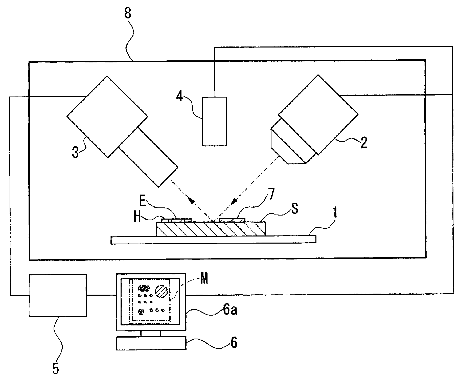
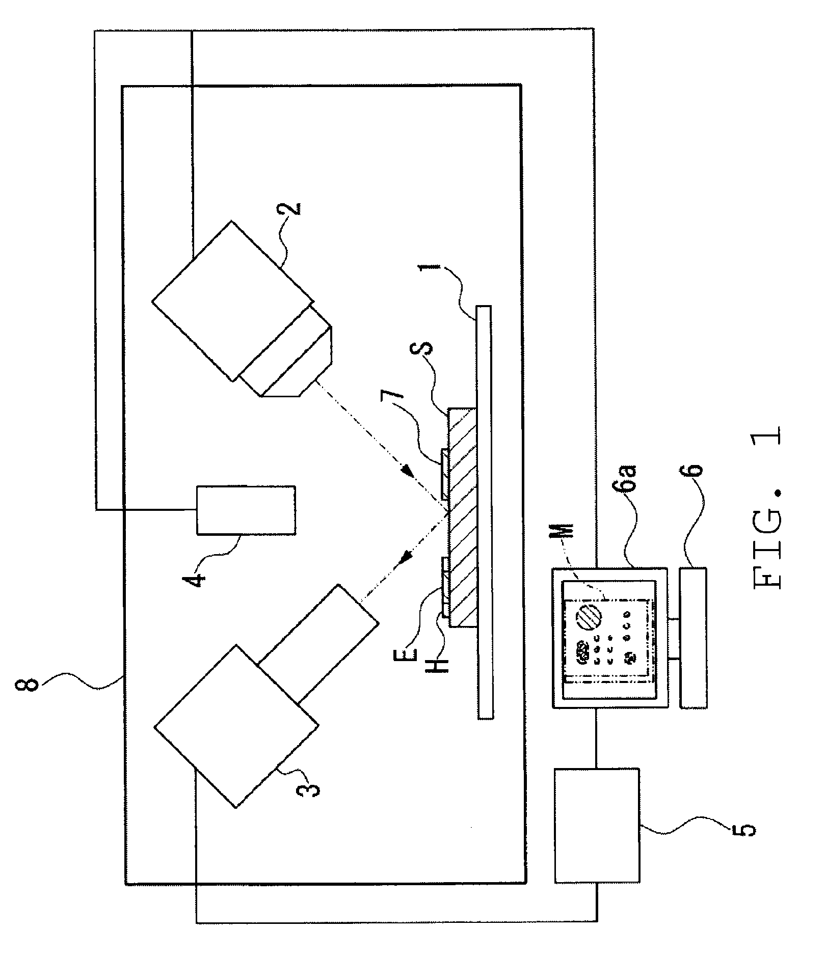
[0035]The X-ray analysis apparatus according to this embodiment is, for example, an energy dispersive fluorescent X-ray analysis apparatus, and as illustrated in FIG. 1 and FIG. 2, includes: a movable sample stage (moving mechanism) 1 for placing a sample S thereon and moving the sample S; an X-ray tubular bulb (radiation source) 2 for irradiating a primary X-ray (radiation beam) X1 to an arbitrary irradiation point located on the sample S; an X-ray detector 3 for detecting a characteristic X-ray and a scattered X-ray which are radiated from the sample S and outputting a signal containing energy information on the characteristic X-ray and the scatter...


PUM

PropertyMeasurementUnit
energyaaaaaaaaaa
coloraaaaaaaaaa
concentrationaaaaaaaaaa

Abstract

Provided is an X-ray analysis apparatus including: an X-ray tubular bulb for irradiating a sample with a radiation beam; an X-ray detector for detecting a characteristic X-ray and a scattered X-ray and outputting a signal containing energy information on the characteristic X-ray and the scattered X-ray; an analyzer for analyzing the signal; a sample stage capable of moving an irradiation point relatively with respect to the sample within a mapping area set in advance; and an X-ray mapping processing section for discriminating an X-ray intensity corresponding to a specific element, determining an intensity contrast in which a color or lightness is changed in accordance with the X-ray intensity, and for performing image display at a position corresponding to the irradiation point, in which the X-ray mapping processing section determines the intensity contrast of the X-ray intensity at the irradiation point by setting in advance the X-ray intensity discriminated as to a reference material in which a component element and a concentration thereof are known as a reference.

Description

RELATED APPLICATIONS[0001]This application claims priority under 35 U.S.C. §119 to Japanese Patent Application Nos. JP2008-172006 filed on Jul. 1, 2008 and JP2008-277731 filed on Oct. 29, 2008, the entire contents of which are hereby incorporated by reference.BACKGROUND OF THE INVENTION[0002]1. Field of the Invention[0003]The present invention relates to an X-ray analysis apparatus and an X-ray analysis method which are suitable for performing an X-ray mapping analysis on a surface of a sample through, for example, a fluorescent X-ray analysis.[0004]2. Description of the Related Art[0005]A fluorescent X-ray analysis is used to perform a qualitative analysis or a quantitative analysis of a sample by radiating the sample with an X-ray emitted from an X-ray source, detecting a fluorescent X-ray which is a characteristic X-ray emitted from the sample with an X-ray detector, and by obtaining a spectrum from energy of the fluorescent X-ray. The Fluorescent X-ray analysis enables the non-d...

Claims


Application Information

Patent Timeline
Patent Type & Authority Applications(United States)
IPC IPC(8): G01N23/223G01N23/04G01N23/201
CPCG01N2223/076G01N23/223
Inventor MATOBA, YOSHIKINAGASAWA, KANJI
Owner HITACHI HIGH TECH SCI CORP
Why Eureka
Try Eureka