
X-ray analysis apparatus and X-ray analysis method

a technology of x-ray analysis and x-ray analysis, which is applied in the direction of material analysis using wave/particle radiation, x/gamma/cosmic radiation measurement, instruments, etc., can solve the problem of difficult to recognize the distribution of elements, and achieve the effect of visual recognition with eas

Inactive Publication Date: 2011-11-29
HITACHI HIGH TECH SCI CORP
View PDF9 Cites 3 Cited by
  • Summary
  • Abstract
  • Description
  • Claims
  • Application Information

AI Technical Summary

Benefits of technology

The present invention provides an X-ray analysis apparatus and method that can easily and directly recognize and specify a specific element in an X-ray image. This is achieved by using a reference material with known characteristics, such as a concentration and thickness, and analyzing the X-ray intensity at the irradiation point on a sample. The apparatus includes a radiation source, X-ray detector, analyzer, and X-ray mapping processing section. The X-ray mapping processing section can move the irradiation point relative to the sample within a mapping area set in advance and determine the intensity contrast of the X-ray intensity at the irradiation point by setting the X-ray intensity of a reference material in the mapping area as the reference. This allows for easy visual recognition of the concentration and thickness of a specific element in the X-ray image. The apparatus and method can be used in various fields such as X-ray analysis of semiconductor devices and biological samples.

Problems solved by technology

However, the above-mentioned conventional technology has the following problem.
However, there is no reference of an element concentration, and hence it is difficult to recognize a distribution of an element which has a predetermined concentration or more directly from an image.

Method used


Image

  • X-ray analysis apparatus and X-ray analysis method
  • X-ray analysis apparatus and X-ray analysis method
  • X-ray analysis apparatus and X-ray analysis method

Examples


Embodiment Construction

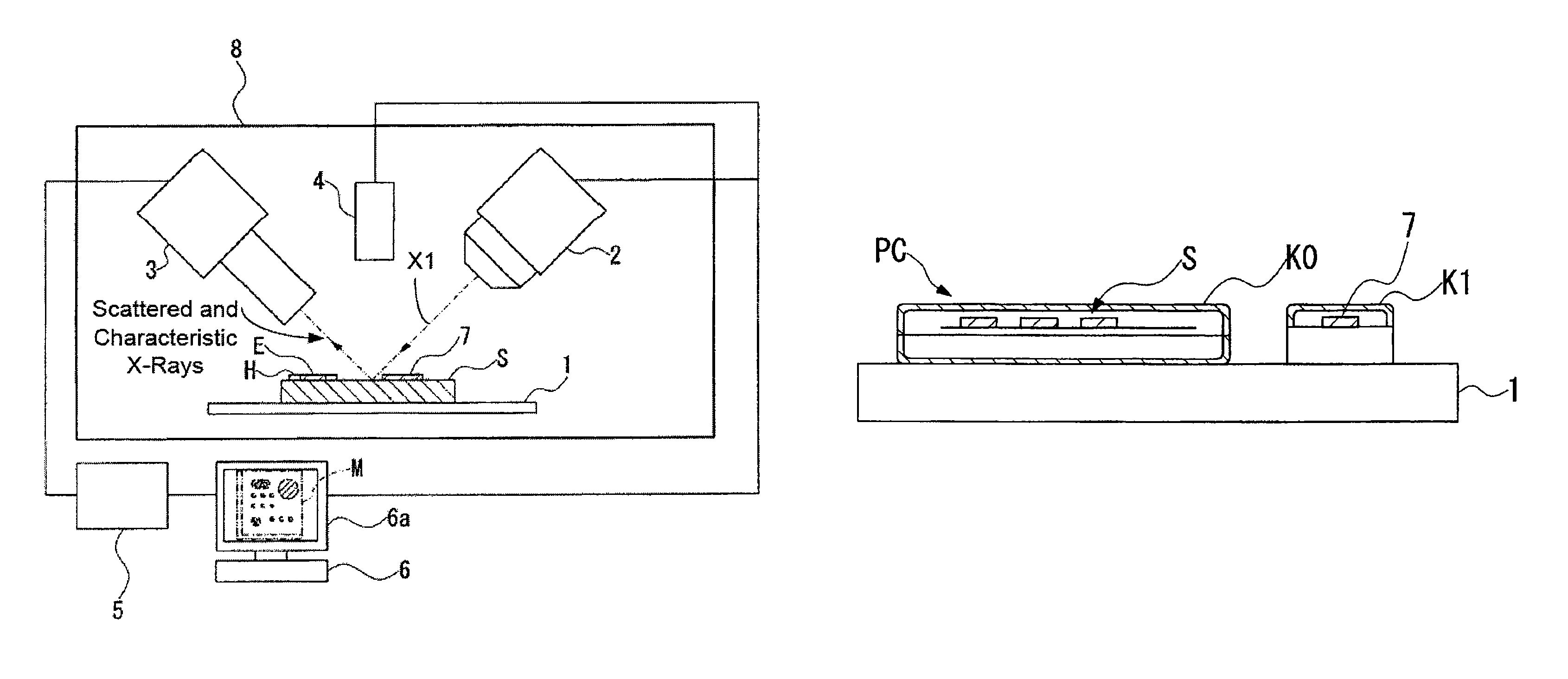
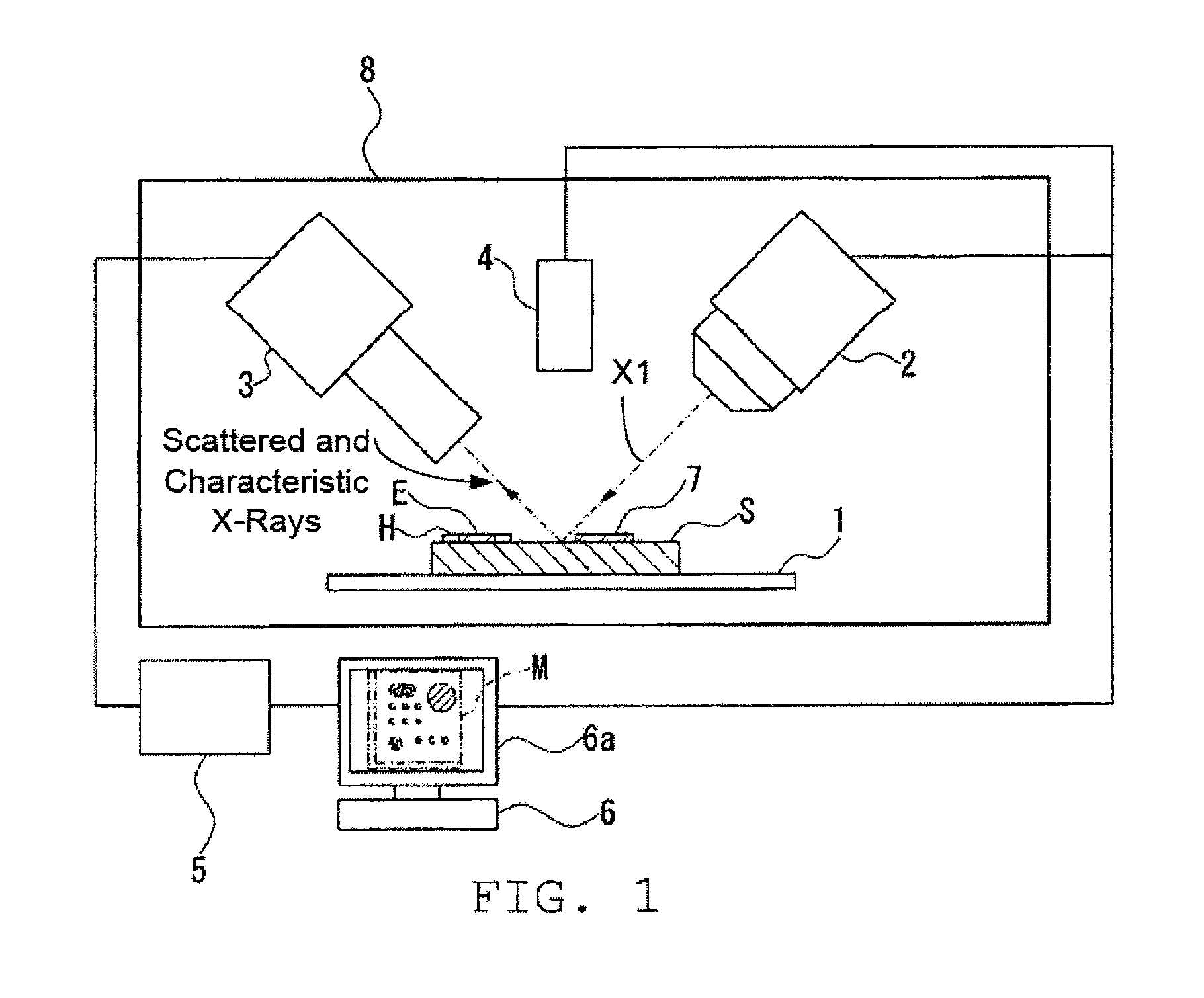
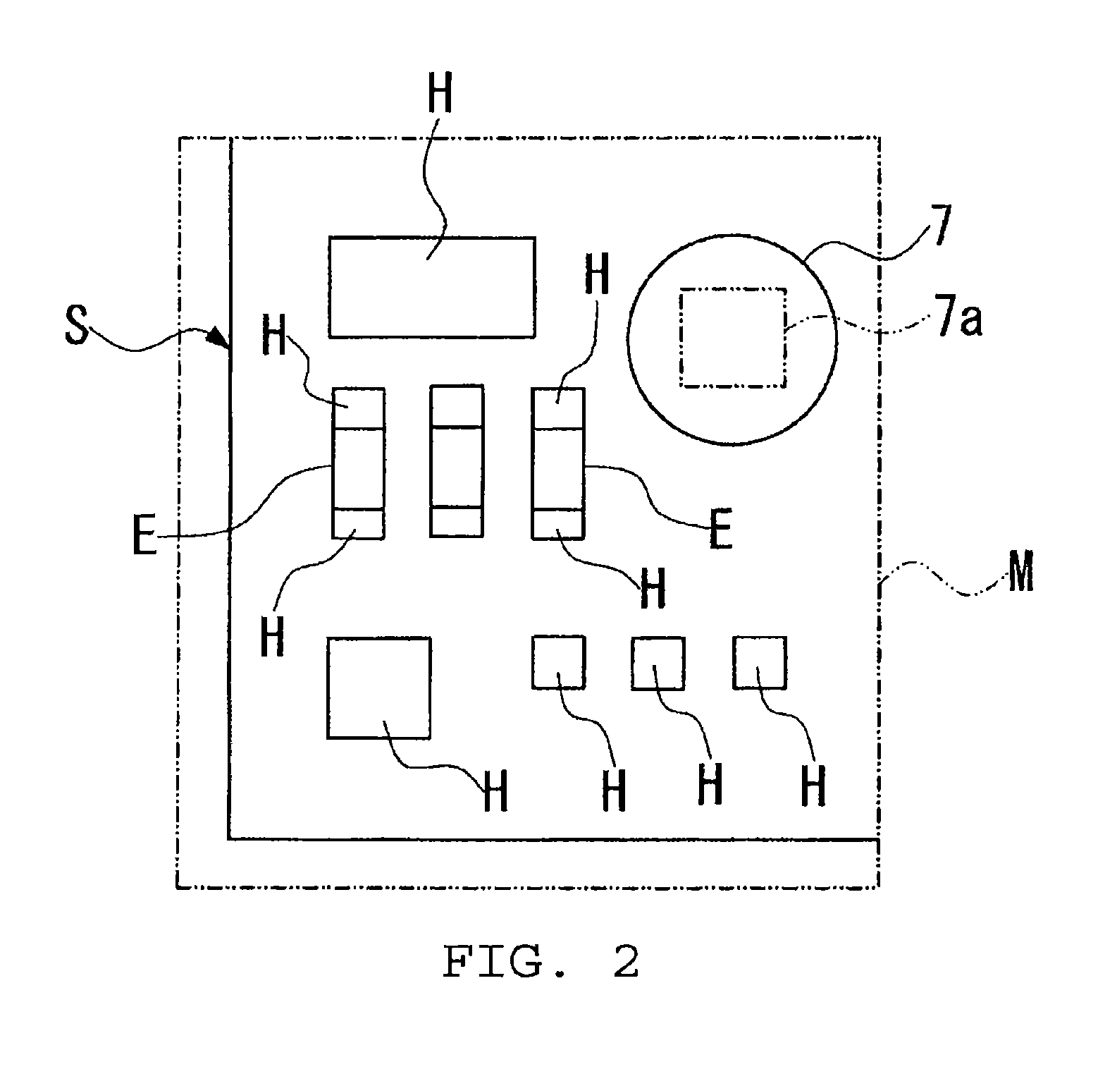
[0034]Hereinafter, an X-ray analysis apparatus and an X-ray analysis method according to an embodiment of the present invention is described with reference to FIGS. 1 to 5. In each of the drawings referred to in the following description, scale size is appropriately changed to illustrate each member in a recognizable manner.

[0035]The X-ray analysis apparatus according to this embodiment is, for example, an energy dispersive fluorescent X-ray analysis apparatus, and as illustrated in FIG. 1 and FIG. 2, includes: a movable sample stage (moving mechanism) 1 for placing a sample S thereon and moving the sample S; an X-ray tubular bulb (radiation source) 2 for irradiating a primary X-ray (radiation beam) X1 to an arbitrary irradiation point located on the sample S; an X-ray detector 3 for detecting a characteristic X-ray and a scattered X-ray which are radiated from the sample S and outputting a signal containing energy information on the characteristic X-ray and the scattered X-ray; an ...


PUM

PropertyMeasurementUnit
energyaaaaaaaaaa
coloraaaaaaaaaa
concentrationaaaaaaaaaa

Abstract

Provided is an X-ray analysis apparatus including: an X-ray tubular bulb for irradiating a sample with a radiation beam; an X-ray detector for detecting a characteristic X-ray and a scattered X-ray and outputting a signal containing energy information on the characteristic X-ray and the scattered X-ray; an analyzer for analyzing the signal; a sample stage capable of moving an irradiation point relatively with respect to the sample within a mapping area set in advance; and an X-ray mapping processing section for discriminating an X-ray intensity corresponding to a specific element, determining an intensity contrast in which a color or lightness is changed in accordance with the X-ray intensity, and for performing image display at a position corresponding to the irradiation point, in which the X-ray mapping processing section determines the intensity contrast of the X-ray intensity at the irradiation point by setting in advance the X-ray intensity discriminated as to a reference material in which a component element and a concentration thereof are known as a reference.

Description

RELATED APPLICATIONS[0001]This application claims priority under 35 U.S.C. §119 to Japanese Patent Application Nos. JP2008-172006 filed on Jul. 1, 2008 and JP2008-277731 filed on Oct. 29, 2008, the entire contents of which are hereby incorporated by reference.BACKGROUND OF THE INVENTION[0002]1. Field of the Invention[0003]The present invention relates to an X-ray analysis apparatus and an X-ray analysis method which are suitable for performing an X-ray mapping analysis on a surface of a sample through, for example, a fluorescent X-ray analysis.[0004]2. Description of the Related Art[0005]A fluorescent X-ray analysis is used to perform a qualitative analysis or a quantitative analysis of a sample by radiating the sample with an X-ray emitted from an X-ray source, detecting a fluorescent X-ray which is a characteristic X-ray emitted from the sample with an X-ray detector, and by obtaining a spectrum from energy of the fluorescent X-ray. The Fluorescent X-ray analysis enables the non-d...

Claims


Application Information

Patent Timeline
Patent Type & Authority Patents(United States)
IPC IPC(8): G01B15/00G01N23/201
CPCG01N23/223G01N2223/076
Inventor MATOBA, YOSHIKINAGASAWA, KANJI
Owner HITACHI HIGH TECH SCI CORP
Learn More