
Tarp roll-up with pivoting radial arms

a radial arm and roll-up technology, applied in the field of tar, can solve the problems of system bind, loose contents may be blown and scattered out, and the contents of the trailer bed may be compromised

Active Publication Date: 2015-01-13
SIOUX CITY TARP
View PDF7 Cites 7 Cited by
  • Summary
  • Abstract
  • Description
  • Claims
  • Application Information

AI Technical Summary

Benefits of technology

The present invention is about a machine that helps spread a tarp over a trailer. It has a part that is attached to the wall of the trailer and a part that supports the tarp roller. The machine has flexible but inelastic arms that are connected to the attachment parts. These arms are designed to prevent the attachment parts from aligning with each other. The technical effect of this invention is that it provides a more efficient and easier way to spread a tarp over a trailer.

Problems solved by technology

Therefore, if the trailer bed is not covered as the trailer is pulled over the road, the loose contents may be blown and scattered out of the open top of the trailer bed.
Additionally, the contents of the trailer bed may be compromised by rain, or other contaminants.
For designs that use a pair of pivotally connected arms to form the radial arms, a problem can arise as the arms move across their length of greatest extent in that precaution must be taken to prevent the arms from pivoting over center, which will cause the system to bind.
However, these solutions could be improved upon by eliminating the springs, which can be relatively expensive and time consuming to install, and by shortening the arms to reduce weight and save material.

Method used


Image

  • Tarp roll-up with pivoting radial arms
  • Tarp roll-up with pivoting radial arms
  • Tarp roll-up with pivoting radial arms

Examples


Embodiment Construction

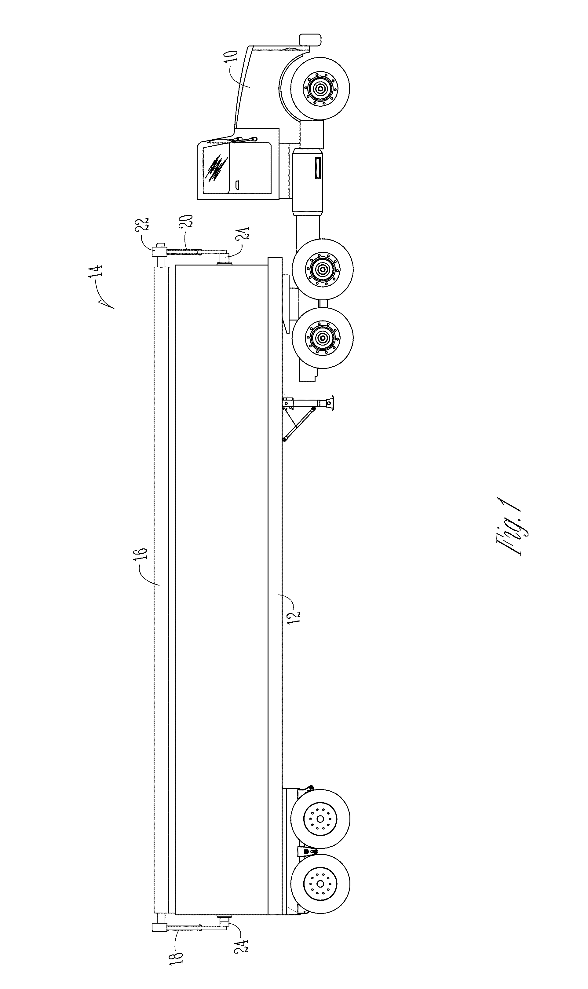
[0016]FIG. 1 shows a truck 10 and trailer 12 provided with a tarp roll-up system 14 according to one embodiment of the present invention. The tarp roll-up system 14 includes a tarp 16 supported between rear and front radial arms 18 and 20. The front radial arm 20 has at its free end a winch-style motor 22 used to roll and unroll the tarp 16 across the top opening of the trailer 12. Each of the radial arms 18 and 20 are pivotally connected to the walls of the trailer 12 via mounting brackets 24.

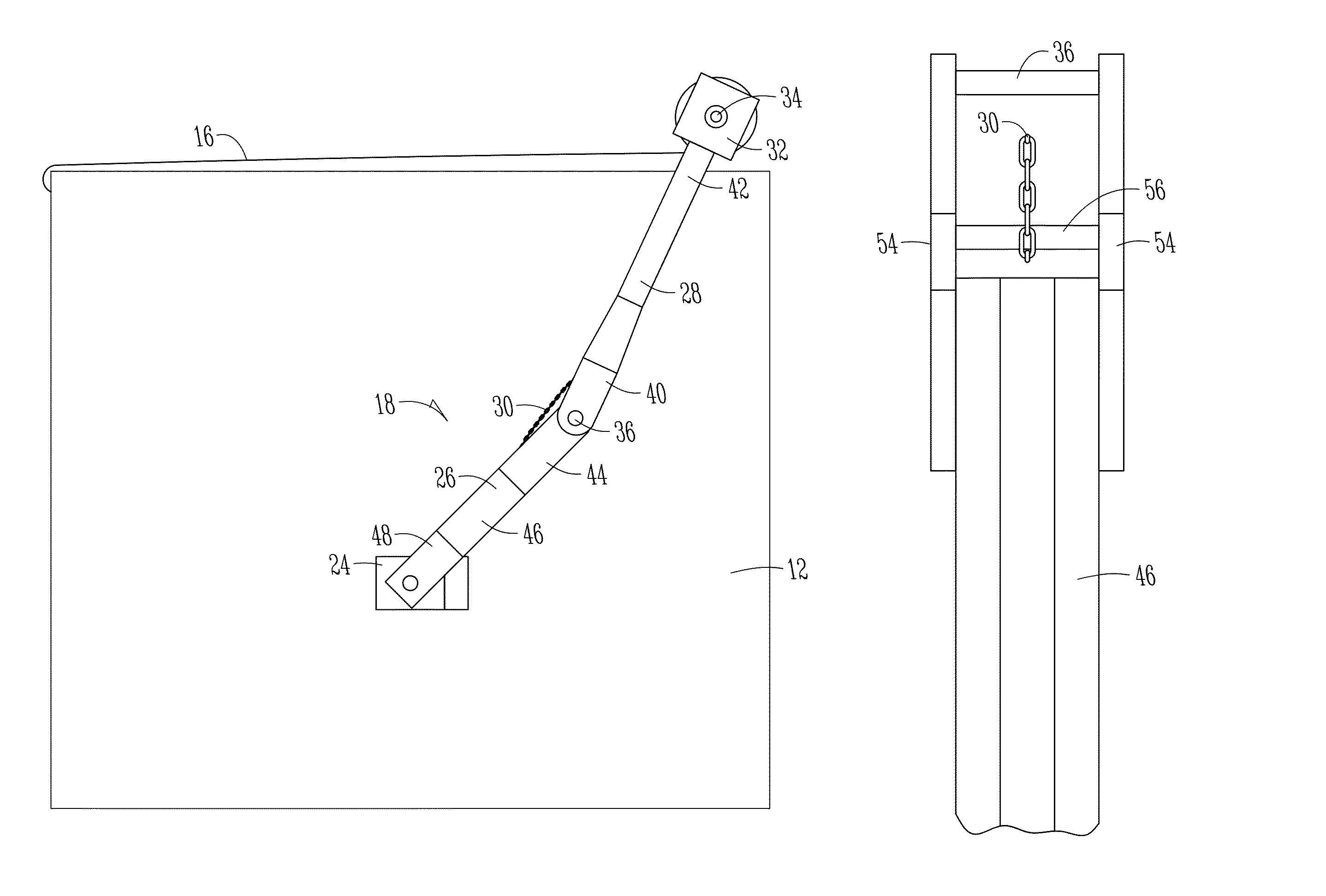
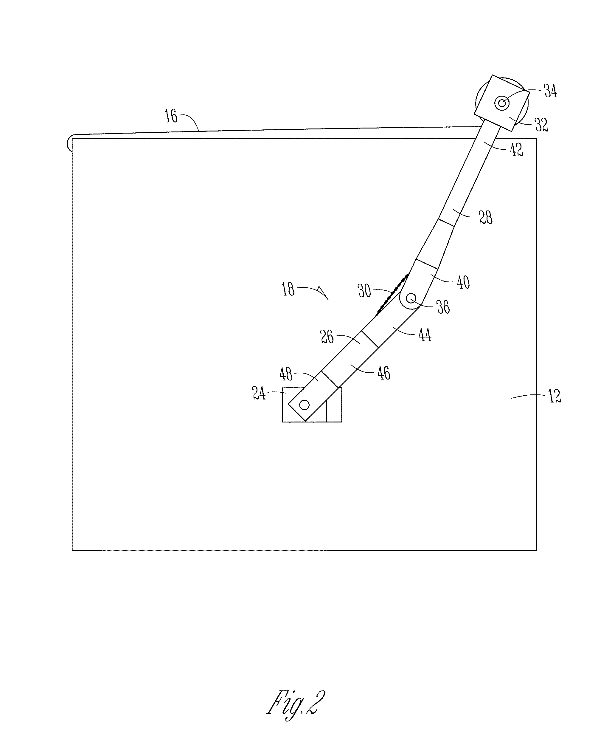
[0017]FIG. 2 shows a rear view of a portion of the trailer 12 and tarp roll-up system 14 from FIG. 1. The rear radial arm 18 comprises a proximal member 26 that is pivotally connected at a constrained end to the bracket 24 at pivot support 48, and pivotally connected by pivot member 36 to a distal member 28 at the moving end of the proximal member 26 at joint member 40. A distal arm member 42 extends from the joint member 40 to operably attach to the connection member 32 that connects the rear...


PUM


Abstract

A tarp deploying apparatus includes radial arm with a proximal arm and a distal arm. A flexible inelastic limit element is provided between the proximal and distal arms to prevent them from crossing over center to an angle that would cause the apparatus to bind.

Description

FIELD OF THE INVENTION[0001]This invention relates generally to the field of tarp deploying devices for use on trailers, and especially to tarp deploying apparatuses that use pivoting radial arms.BACKGROUND OF THE INVENTION[0002]Trailers used to haul loose materials such as dirt, sand, gravel, or grain commonly have beds or tubs that have an open top with generally vertical front and rear walls and sloping sidewalls for retaining contents within the trailer. Therefore, if the trailer bed is not covered as the trailer is pulled over the road, the loose contents may be blown and scattered out of the open top of the trailer bed. Additionally, the contents of the trailer bed may be compromised by rain, or other contaminants. Accordingly, it is known to deploy tarps across the open top space of the trailer beds to cover the contents of the trailer beds.[0003]Several mechanisms have been devised for deploying the tarps across the trailer bed. Many of these devices include radial arms that...

Claims


Application Information

Patent Timeline
Patent Type & Authority Patents(United States)
IPC IPC(8): B60P7/04B60J7/08
CPCB60J7/085
Inventor BREMER, DONALD WILLIAMBERG, TERRY L.
Owner SIOUX CITY TARP
Learn More