Liquid droplet ejection head, image forming apparatus including same, and method for cleaning same

a technology of liquid droplets and ejection heads, which is applied in the field of liquid droplets ejection heads, image forming apparatus including same, and cleaning methods. it can solve the problems of reducing yield, difficult to reliably clean inside the inkjet head, and affecting the quality of image, so as to achieve the minimum necessary cleaning range and achieve the effect of reducing yield and reliably cleaning the minimum necessary rang

Inactive Publication Date: 2015-03-10
RICOH KK
View PDF12 Cites 0 Cited by
  • Summary
  • Abstract
  • Description
  • Claims
  • Application Information

AI Technical Summary

Benefits of technology

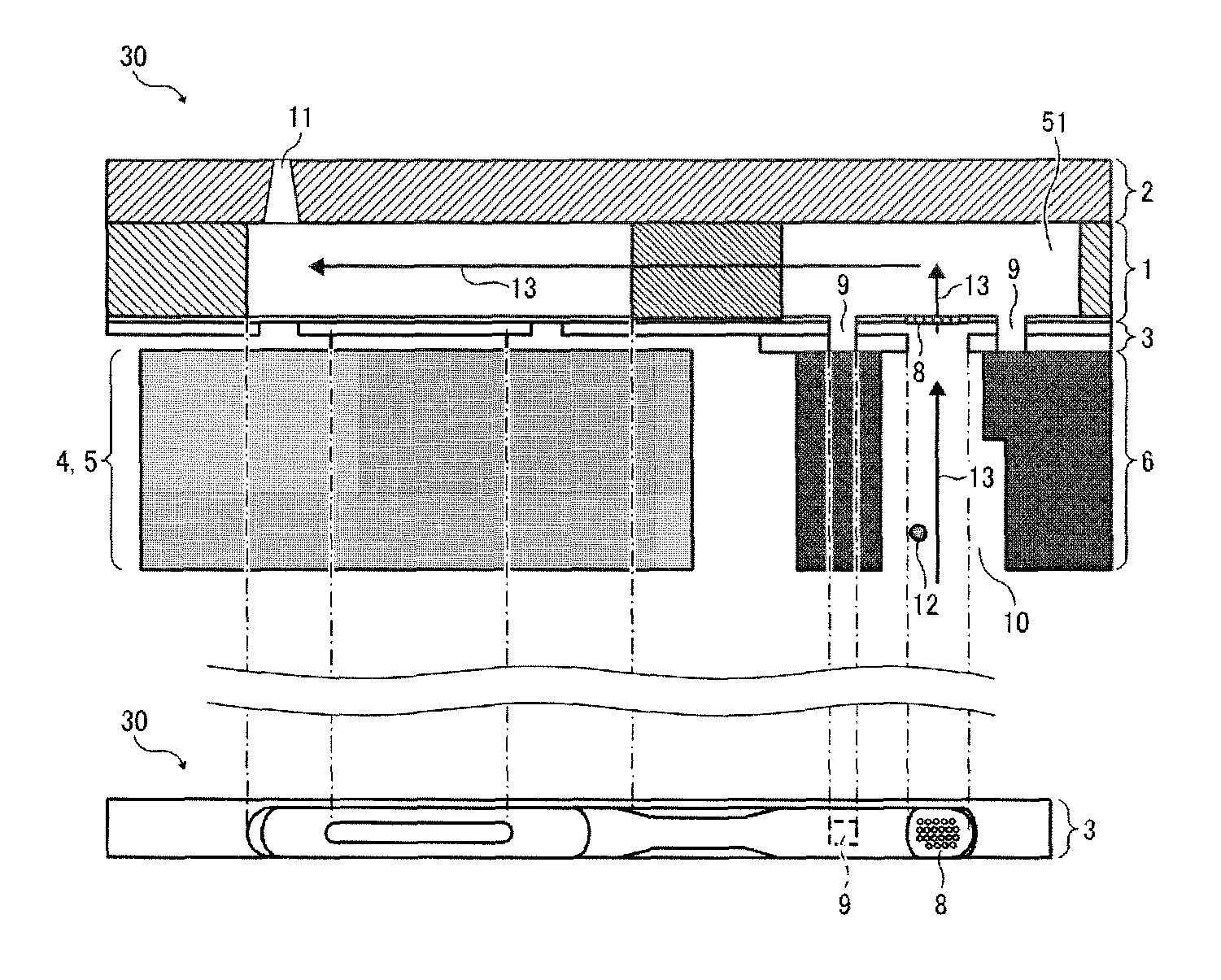
[0010]In view of the foregoing, illustrative embodiments of the present invention provide a novel liquid droplet ejection head in which both a filter and a liquid discharge opening are provided to individual liquid chambers to reliably clean the minimum necessary cleaning range of the liquid droplet ejection head without decreasing yield. The illustrative embodiments also provide an inkjet-type image forming apparatus including the liquid droplet ejection head, and a method for cleaning the liquid droplet ejection head.

Problems solved by technology

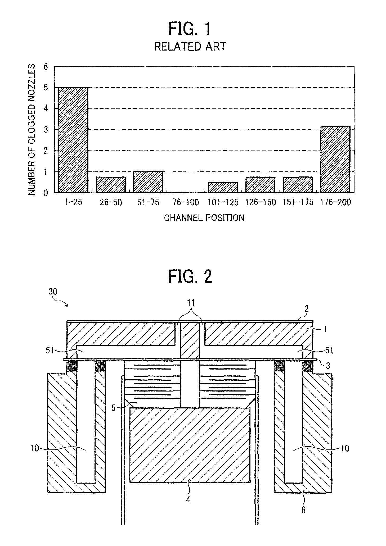
In the inkjet-type image forming apparatus, foreign substances that inadvertently enter the inkjet head during manufacture or with a liquid such as ink dispensed from an ink cartridge to the inkjet head can cause clogging of the nozzles and irregular ejection of ink droplets from the nozzles, thereby degrading image quality.
However, because the cleaning opening is provided to the common liquid chamber in the related-art image forming apparatus, it is difficult to reliably clean inside the inkjet head.
However, although providing the filter to the individual liquid chambers is well known, foreign substances are trapped within the individual liquid chambers in such a configuration, thereby possibly reducing yield.

Method used


Image

  • Liquid droplet ejection head, image forming apparatus including same, and method for cleaning same
  • Liquid droplet ejection head, image forming apparatus including same, and method for cleaning same
  • Liquid droplet ejection head, image forming apparatus including same, and method for cleaning same

Examples


Embodiment Construction

[0036]In describing illustrative embodiments illustrated in the drawings, specific terminology is employed for the sake of clarity. However, the disclosure of this patent specification is not intended to be limited to the specific terminology so selected, and it is to be understood that each specific element includes all technical equivalents that operate in a similar manner and achieve a similar result.

[0037]Illustrative embodiments of the present invention are now described below with reference to the accompanying drawings.

[0038]In a later-described comparative example, illustrative embodiment, and exemplary variation, for the sake of simplicity the same reference numerals will be given to identical constituent elements such as parts and materials having the same functions, and redundant descriptions thereof omitted unless otherwise required.

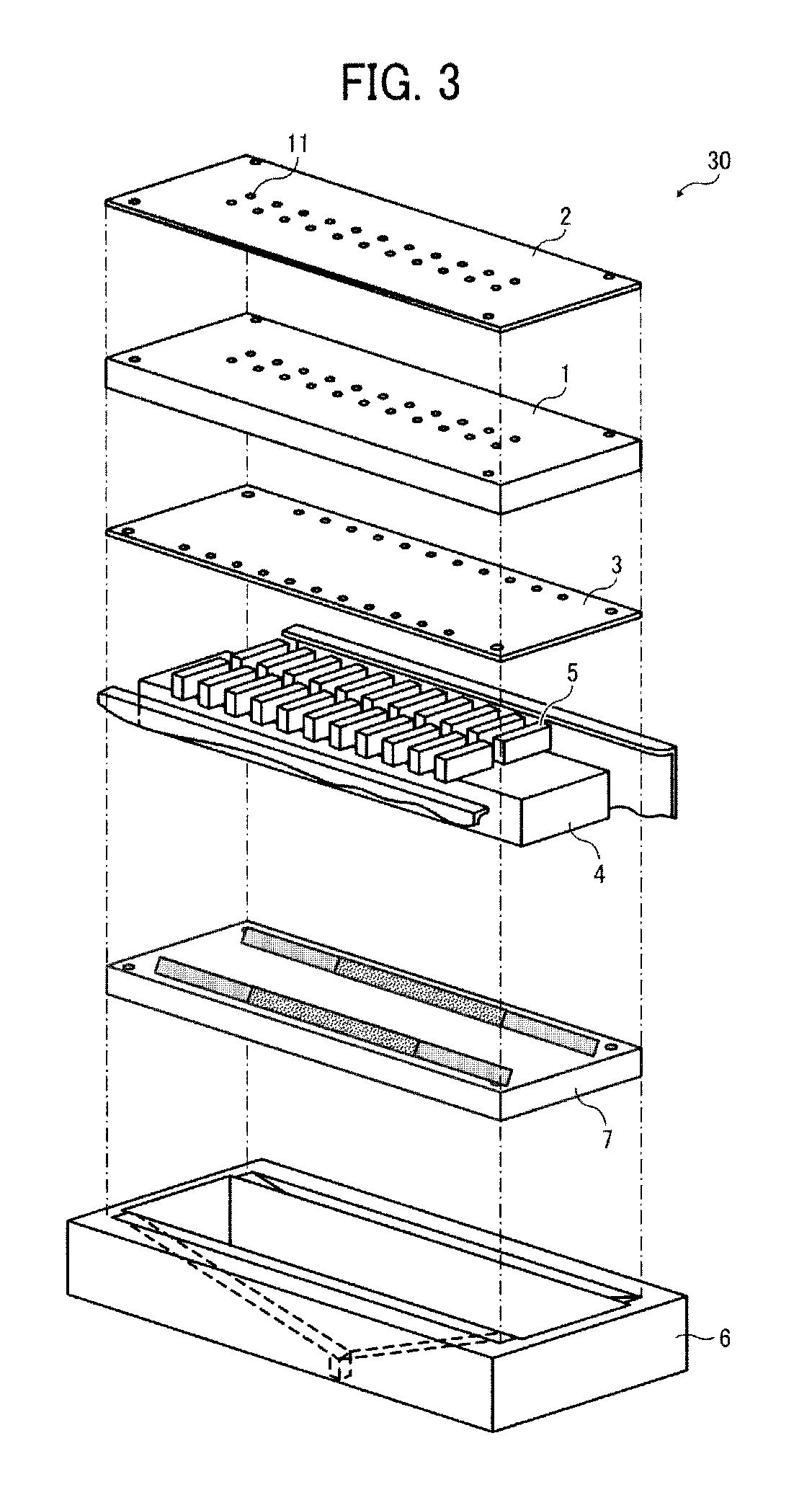
[0039]A configuration of a liquid droplet ejection head 30 according to illustrative embodiments is described in detail below with reference ...


PUM


Abstract

A liquid droplet ejection head including a common liquid chamber, multiple individual liquid chambers communicating with the common liquid chamber, to which a liquid is supplied via the common liquid chamber, a nozzle plate containing multiple nozzles communicating with the multiple individual liquid chambers to eject the liquid, a filter disposed within a passageway between the common liquid chamber and the multiple individual liquid chambers to remove foreign substances from the liquid, and a through-hole provided adjacent to the filter to communicate with the multiple individual liquid chambers, and sealed by a frame member in which the common liquid chamber is formed.

Description

CROSS-REFERENCE TO RELATED APPLICATIONS[0001]The present patent application is based on and claims priority pursuant to 35 U.S.C. §119 from Japanese Patent Application Nos. 2010-281266, filed on Dec. 17, 2010, and 2011-103633, filed on May 6, 2011, both in the Japan Patent Office, each of which is incorporated by reference herein in its entirety.BACKGROUND OF THE INVENTION[0002]1. Field of the Invention[0003]This invention relates generally to a liquid droplet ejection head provided with a filter to remove foreign substances from the liquid, an image forming apparatus including the liquid droplet ejection head, and a method for cleaning the liquid droplet ejection head.[0004]2. Description of the Background Art[0005]In general, a liquid droplet ejection head such as an inkjet head employed in an inkjet-type image forming apparatus includes liquid chambers and multiple nozzles each having a diameter of 10 μm. In the inkjet-type image forming apparatus, foreign substances that inadver...

Claims


Application Information

Patent Timeline
Patent Type & Authority Patents(United States)
IPC IPC(8): B41J2/165B41J2/14
CPCB41J2/14274B41J2002/14403
Inventor KAMITO, TAKAOISHIDA, HIROYA
Owner RICOH KK
Why Eureka
Try Eureka