Fly jib for a crane and method of use

a technology of flying jib and crane, which is applied in the field of cranes, can solve the problem that the flying jib does not have a rotation mechanism

Active Publication Date: 2015-03-17
SKYCRANE LLC
View PDF14 Cites 20 Cited by
  • Summary
  • Abstract
  • Description
  • Claims
  • Application Information

AI Technical Summary

Problems solved by technology

A problem exist however in that the fly jib has no rotation mechanism, and as such must be manually rotated by personnel using long poles to align the load with the target area.

Method used


Image

  • Fly jib for a crane and method of use
  • Fly jib for a crane and method of use
  • Fly jib for a crane and method of use

Examples


Embodiment Construction

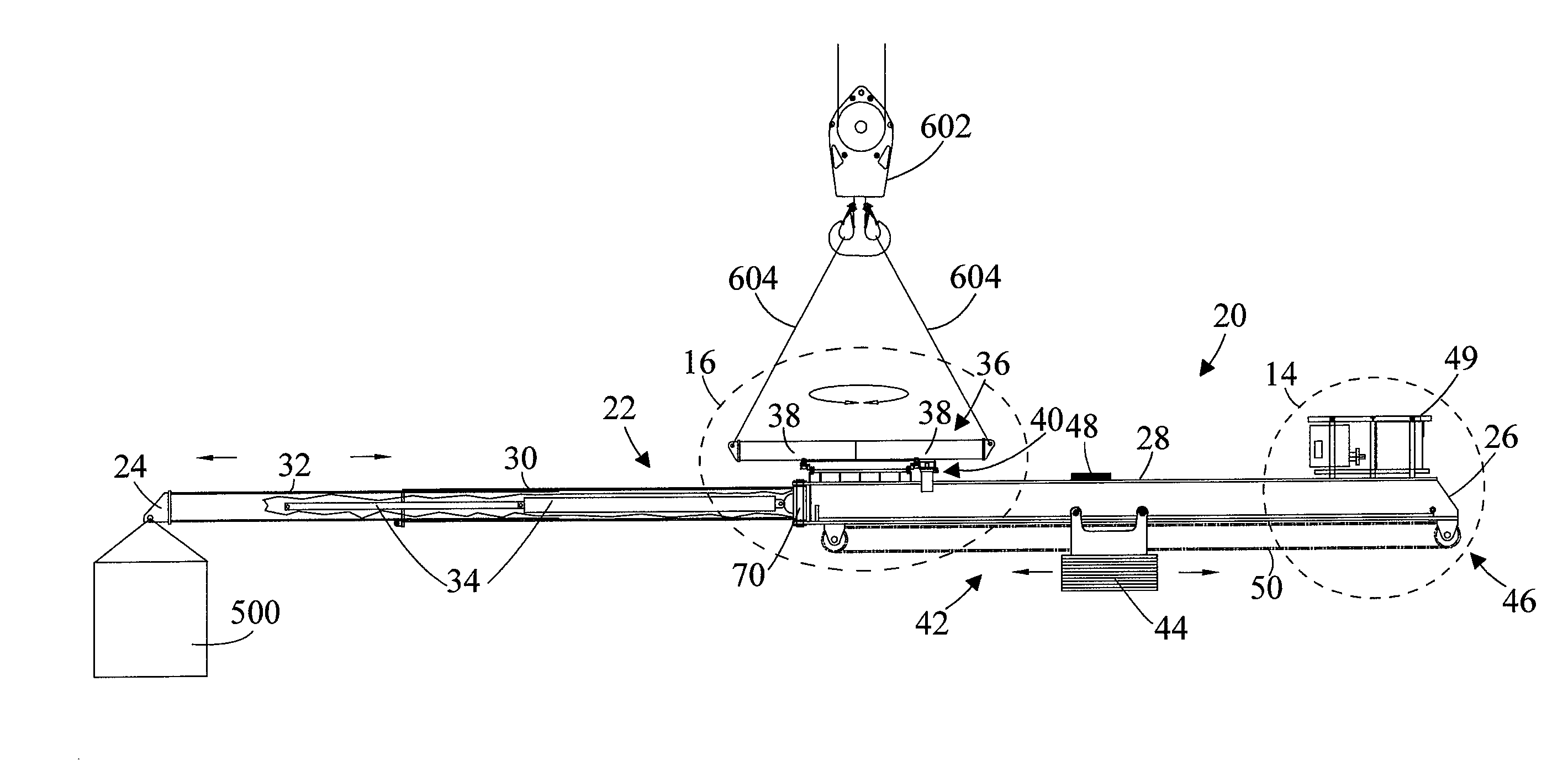
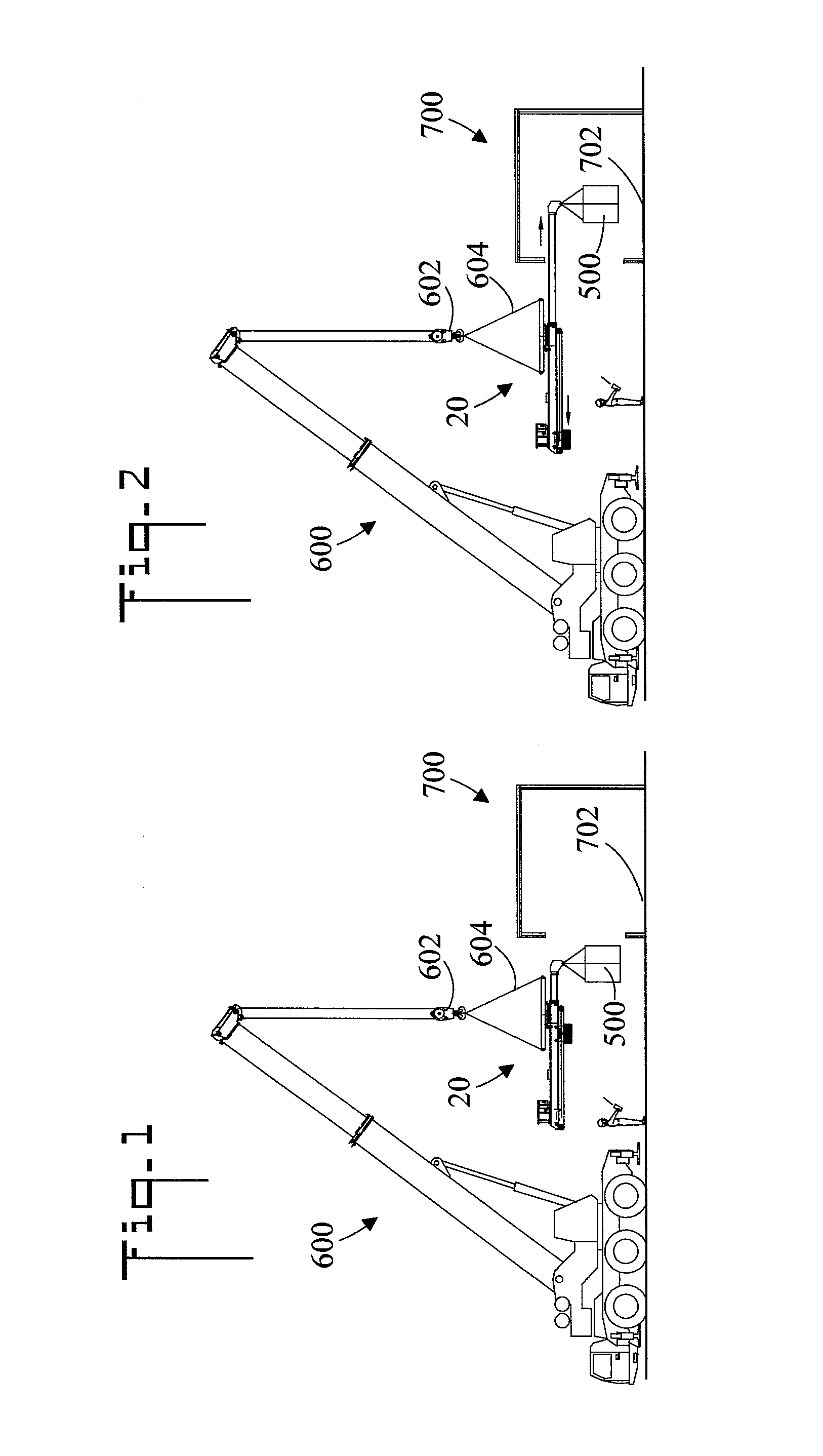
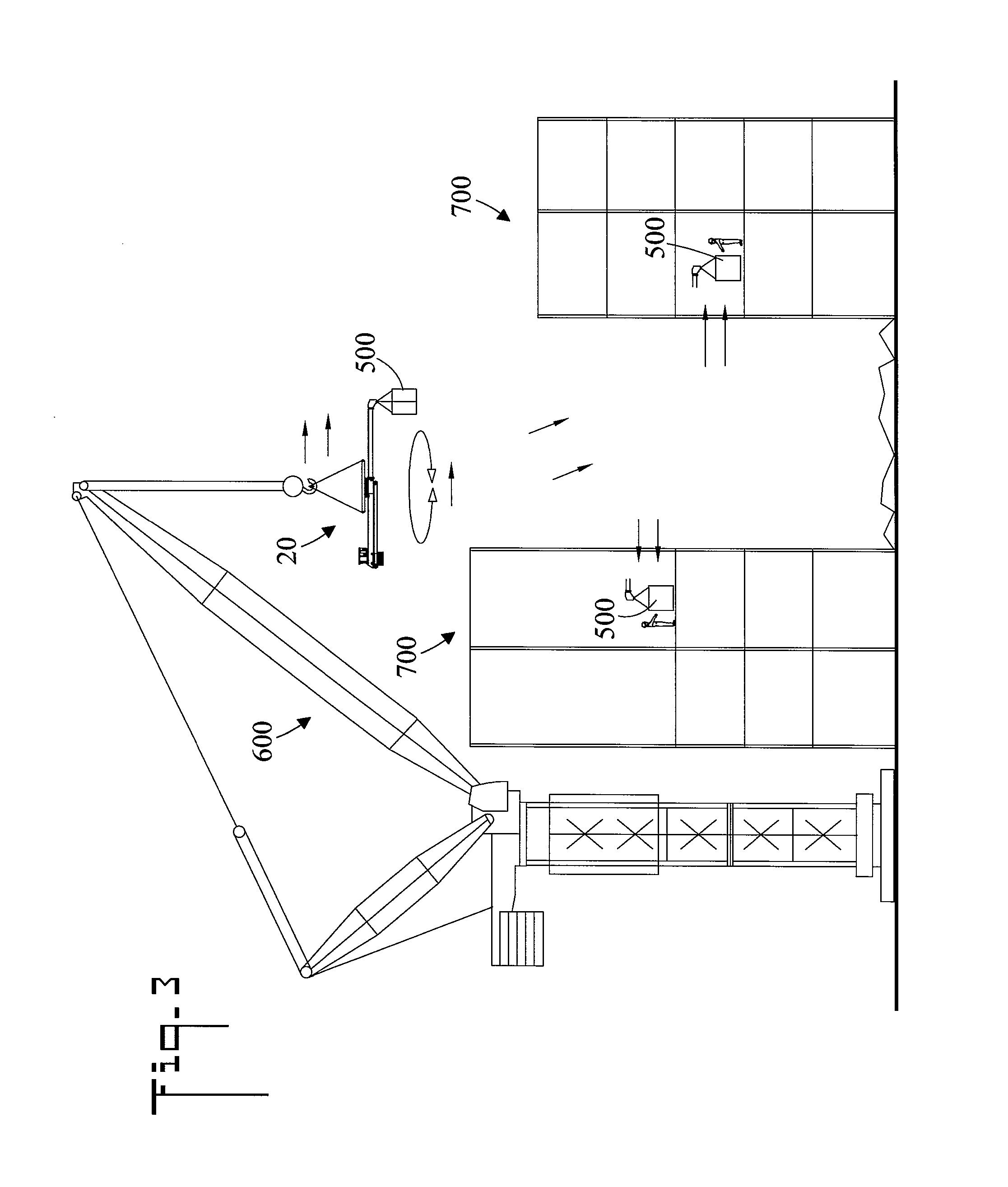
[0034]Referring initially to FIGS. 1-3, there are illustrated reduced side elevation views of a fly jib 20 in accordance with the present invention being used to place a load 500 inside a building 700 having a target area 702. Fly jib 20 cooperates with a ground crane 600 having a load block 602. Fly jib 20 is connected to load block 602 by four rope slings 604. Load block 602 and slings 604 allow fly jib 20 to be positioned for load pick-up and movements to required locations inside building or cavities. Fly jib 20 is held horizontal by a balance mechanism which includes a travelling counterweight which balances the weight of the load that is being lifted. Fly jib 20 stays in the horizontal position as it is moves and operates. FIGS. 1 and 2 show ground crane 600 positioning load 500 inside a building 700. In FIG. 1 fly jib 20 is maneuvered into position so that load 500 is ready to enter building 700 and be placed on target area 702. In FIG. 2 the operator with radio remote contro...


PUM


Abstract

A fly jib for a crane having a load block includes a variable length beam to which a load can be connected. A rotation mechanism is connected to the variable length beam, and is connectable to the load block so that said rotational mechanism can selectively rotate the variable length beam with respect to the load block. A balance mechanism is connected to the variable length beam, the balance mechanism automatically keeps the variable length beam in a horizontal position.

Description

CROSS REFERENCE TO RELATED APPLICATION[0001]NoneTECHNICAL FIELD[0002]The present invention pertains generally to cranes and the use of same for moving loads, and more particularly to a fly jib which is used to position the lifted load.BACKGROUND OF THE INVENTION[0003]A fly jib is a lifting device which assists a crane operator in picking and placing a load at a target area. A fly jib is particularly useful in that it allows the crane operator to place the load, such as construction materials, inside a multistory building. A problem exist however in that the fly jib has no rotation mechanism, and as such must be manually rotated by personnel using long poles to align the load with the target area. Additionally, the fly jib does not have a way of extending its length so that the load can be moved toward the target area without having to move the supporting crane.BRIEF SUMMARY OF THE INVENTION[0004]The present invention is directed to a fly jib which overcomes the problems of prior art...

Claims


Application Information

Patent Timeline
Patent Type & Authority Patents(United States)
IPC IPC(8): B66C1/10B66C23/42B66C23/62
CPCB66C23/42B66C23/62B66C1/105B66C13/08B66C13/40
Inventor HATTON, II, GARY MICHAEL
Owner SKYCRANE LLC
Why Eureka
Try Eureka