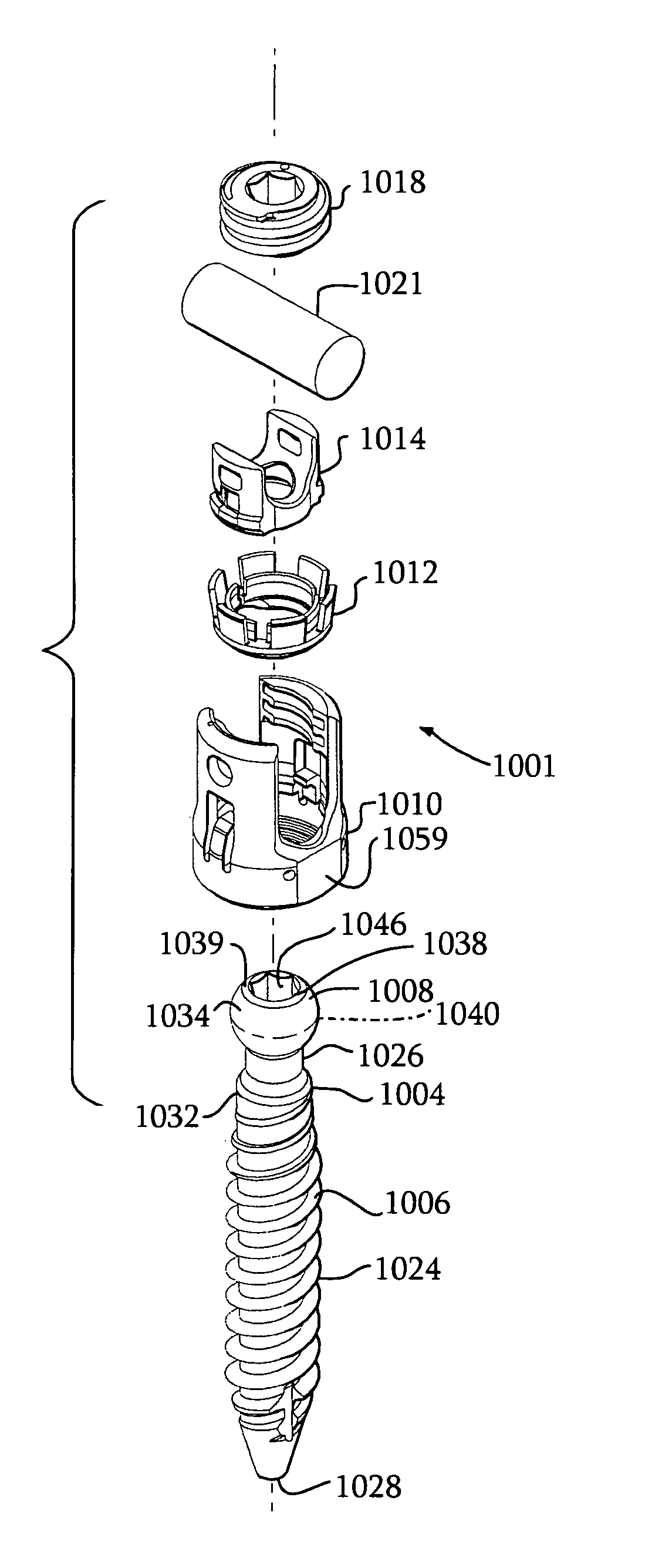
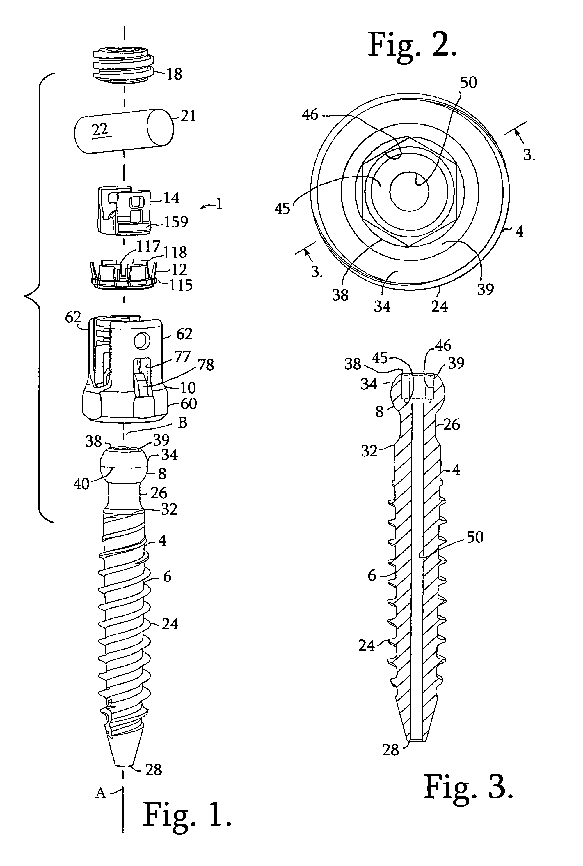
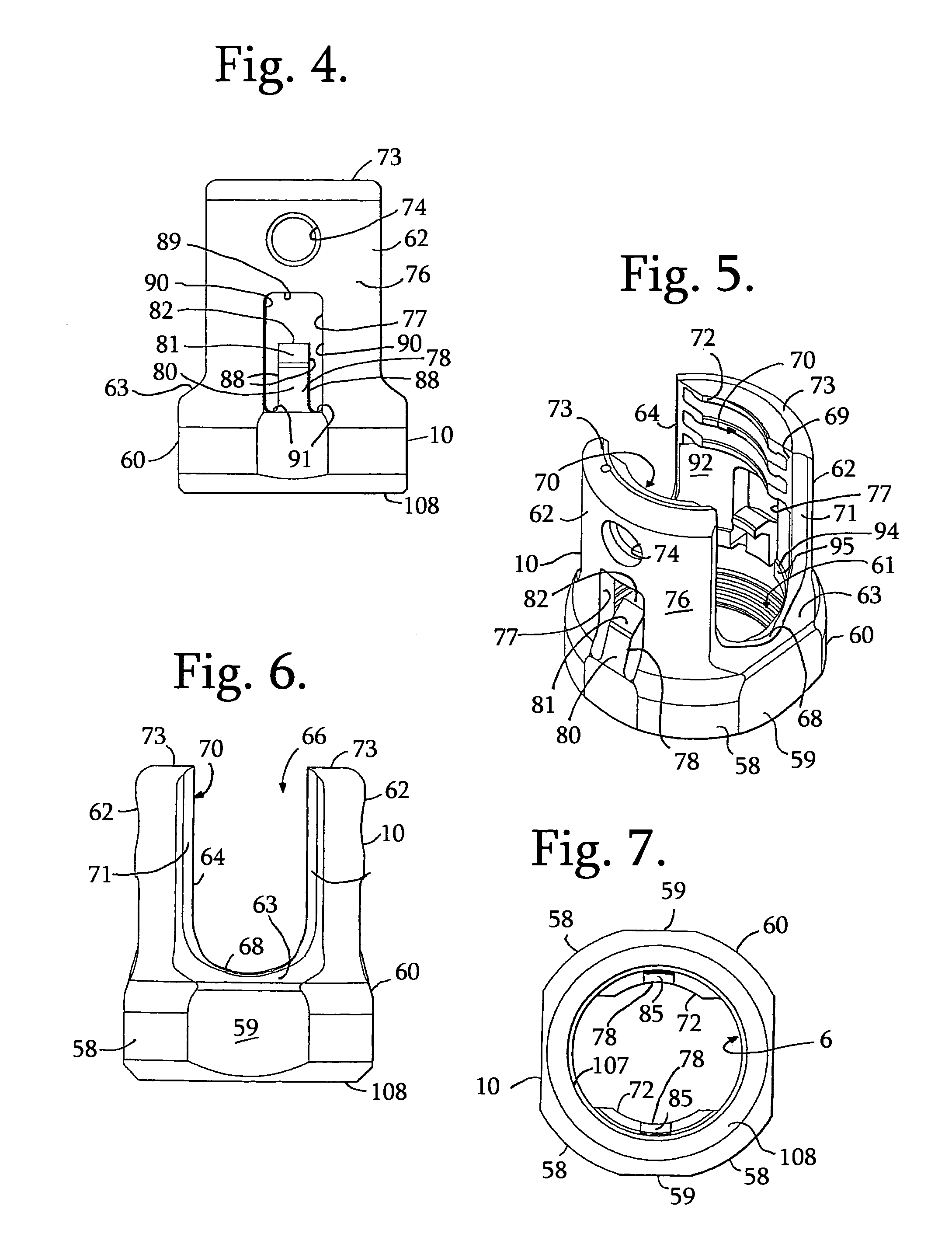
[0012]The expansion-only retainer ring base portion in the present invention is positioned entirely below the shank head hemisphere in the receiver and can be a stronger, more substantial structure to resist larger pull out forces on the assembly. The retainer ring base can also be better supported on a generally horizontal loading surface near the lower opening in the bottom of the receiver. This design has been found to be stronger and more secure when compared to that of the prior art which uses some type of contractile locking engagement between the parts, as described above; and, again, once assembled it cannot be disassembled.
[0013]Thus, a polyaxial bone screw assembly according to the invention includes a shank having an integral upper portion or integral radiused or spherical head and a body for fixation to a bone; a separate receiver defining an upper open channel, a central bore, a lower cavity and a lower opening; a top drop and turn in place lower compression insert; and a friction fit resilient expansion locking split retainer for capturing the shank head in the receiver lower cavity, the shank head being frictionally engaged with, but still movable in a non-floppy manner with respect to the friction fit retainer and the receiver prior to locking of the shank into a desired configuration. The shank is finally locked into a fixed position relative to the receiver by frictional engagement between the insert and a lower split ring-like portion of the retainer, as described previously, due to a downward force placed on the compression insert by a closure top pressing on a rod, or other longitudinal connecting member, captured within the receiver bore and channel. In the illustrated embodiments, retainers and compression inserts are downloaded into the receiver, but uploaded embodiments are also foreseen. The shank head can be positioned into the receiver lower cavity at the lower opening thereof prior to or after insertion of the shank into bone. In some embodiments, the compression insert may include a lock and release feature for independent locking of the polyaxial mechanism so the screw can be used like a fixed monoaxial screw. Also, in some embodiments the shank can be cannulated for minimally invasive surgery applications. The retainer includes upwardly extending tangs that are deployed in the receiver cavity so that the retainer and captured shank head are stabilized and retained in the region of the receiver locking chamber once, but are free to rotate within the cavity. In this way, the shank head and retainer are partially constrained and cannot go back up into the receiver cavity, but can be manipulated there-within.
[0014]Again, a pre-assembled receiver, compression insert and friction fit split retainer may be “pushed-on”, “snapped-on” or “popped-on” to the shank head prior to or after implantation of the shank into a vertebra. Such a “snapping on” procedure includes the steps of uploading the shank head into the receiver lower opening, the shank head pressing against the base portion of the split retainer ring and expanding the resilient lower open retainer portion out into an expansion portion or chamber of the receiver cavity followed by an elastic return of the retainer back to a nominal or near nominal shape thereof after the hemisphere of the shank head or upper portion passes through the lower ring-like portion of the retainer. The shank head enters into friction fit engagement with portions of the retainer, defined at least in part, by inner tangs of the retainer. The retainer snapping onto the shank head as the retainer returns to a neutral or close to neutral orientation, providing a non-floppy connection between the retainer and the shank head. In the illustrated embodiments, when the shank is ultimately locked between the compression insert and the lower portion of the retainer, a lower retainer edge surface locks against the shank head. The final fixation occurs as a result of a locking expansion-type of contact between the shank head and the lower edge portion of the split retainer and an expansion-type of non-tapered locking engagement between the lower portion of the retainer ring and the locking chamber in the lower portion of the receiver cavity. The retainer can expand more in the upper portion or expansion chamber of the receiver cavity to allow the shank head to pass through, but has restricted expansion to retain the shank head when the retainer lower ring portion is against the locking chamber surfaces in the lower portion of the receiver cavity and the shank head is forced down against the retainer ring during final locking. In some embodiments, when the polyaxial mechanism is locked, the pressure or compression insert is forced or wedged against a surface of the receiver resulting in an interference locking engagement, allowing for adjustment or removal of the rod or other connecting member without loss of a desired angular relationship between the shank and the receiver. This independent locking feature allows the polyaxial screw to function like a fixed monoaxial screw.