Polyaxial bone anchors with pop-on shank, fully constrained friction fit retainer and lock and release insert
What is Al technical title?
Al technical title is built by PatSnap Al team. It summarizes the technical point description of the patent document.
a technology of polyaxial bone and pop-on shank, which is applied in the field of spinal surgery, can solve the problems of collection-like structures and weak respect, and achieve the effects of good rotational stability, easy use and inexpensive production
Active Publication Date: 2015-04-07
JACKSON ROGER P
View PDF1645 Cites 42 Cited by
Summary
Abstract
Description
Claims
Application Information
AI Technical Summary
This helps you quickly interpret patents by identifying the three key elements:
Problems solved by technology
Method used
Benefits of technology
[0011]The expansion-only retainer ring base in the present invention is positioned entirely below the shank head hemisphere in the receiver and can be a stronger, more substantial structure to resist larger pull out forces on the assembly. The retainer ring base can also be better supported on a generally horizontal loading surface near the lower opening in the bottom of the receiver. This design has been found to be stronger and more secure when compared to that of the prior art which uses some type of contractile locking engagement between the parts, as described above; and, again, once assembled it cannot be disassembled.
[0013]Again, a pre-assembled receiver, compression insert and friction fit split retainer may be “pushed-on”, “snapped-on” or “popped-on” to the shank head prior to or after implantation of the shank into a vertebra. Such a “snapping on” procedure includes the steps of uploading the shank head into the receiver lower opening, the shank head pressing against the base portion of the split retainer ring and expanding the resilient lower open retainer portion out into an expansion portion or chamber of the receiver cavity followed by an elastic return of the retainer back to an original or nominal shape thereof after the hemisphere of the shank head or upper portion passes through the lower ring-like portion of the retainer. The shank head also enters into the friction fit upper portion or super structure of the retainer, the panels of the friction fit portion of the retainer snapping onto the shank head as the retainer returns to a neutral or close to neutral orientation, providing a non-floppy connection between the retainer and the shank head. The friction fit between the shank head and the retainer is temporary and not part of the final locking mechanism. In the illustrated embodiment, when the shank is ultimately locked between the compression insert and the lower portion of the retainer, the friction fit collet-like panels of the retainer are no longer in a friction fit engagement with the shank head and they are not in contact with the receiver. The final fixation occurs as a result of a locking expansion-type of contact between the shank head and the lower portion of the split retainer and an expansion-type of non-tapered locking engagement between the lower portion of the retainer ring and the locking chamber in the lower portion of the receiver cavity. The retainer can expand more in the upper portion or expansion chamber of the receiver cavity to allow the shank head to pass through, but has restricted expansion to retain the shank head when the retainer lower ring portion is against the locking chamber surfaces in the lower portion of the receiver cavity and the shank head is forced down against the retainer ring during final locking. In some embodiments, when the polyaxial mechanism is locked, the insert is wedged against a surface of the receiver resulting in a tapered locking engagement, allowing for adjustment or removal of the rod or other connecting member without loss of a desired angular relationship between the shank and the receiver. This independent locking feature allows the polyaxial screw to function like a fixed monoaxial screw.
[0015]It is noted that once the shank head is captured by the retainer ring and the retainer and head are moved down into the locking chamber region of the receiver cavity, retainer spring tabs are deployed outwardly stabilizing the retainer so that the retainer cannot go back up into the receiver cavity. This spring tab deployment also creates good rotational stability between the retainer and receiver and provides for an additional rotational friction fit between the shank head and the receiver itself since the retainer cannot axially rotate in the receiver.
Problems solved by technology
Collect-like structures extending downwardly from lower pressure inserts, when used in modular polyaxial screw designs, as shown in the prior art, have been found to be somewhat weak with respect to pull-out forces encountered during some spinal reduction procedures.
Method used
Image
Click on the blue label to locate the original text in one second.
Reading with bidirectional positioning of images and text.
Examples
Embodiment Construction
[0057]As required, detailed embodiments of the present invention are disclosed herein; however, it is to be understood that the disclosed embodiments are merely exemplary of the invention, which may be embodied in various forms. Therefore, specific structural and functional details disclosed herein are not to be interpreted as limiting, but merely as a basis for the claims and as a representative basis for teaching one skilled in the art to variously employ the present invention in virtually any appropriately detailed structure. It is also noted that any reference to the words top, bottom, up and down, and the like, in this application refers to the alignment shown in the various drawings, as well as the normal connotations applied to such devices, and is not intended to restrict positioning of the bone attachment structures in actual use.
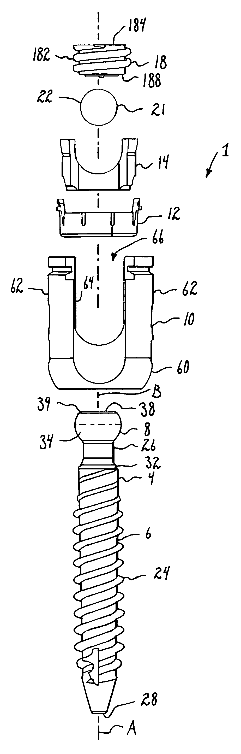
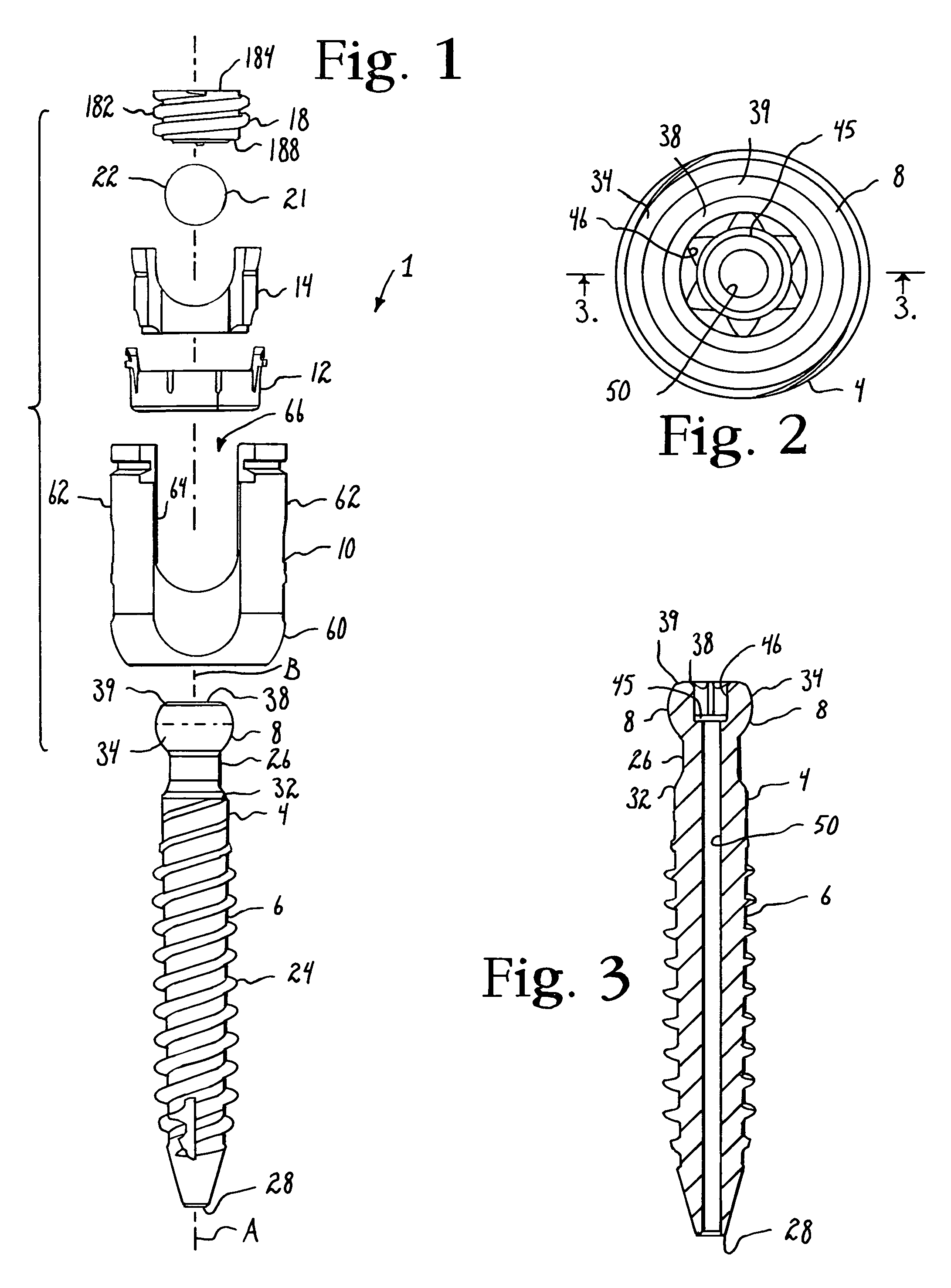
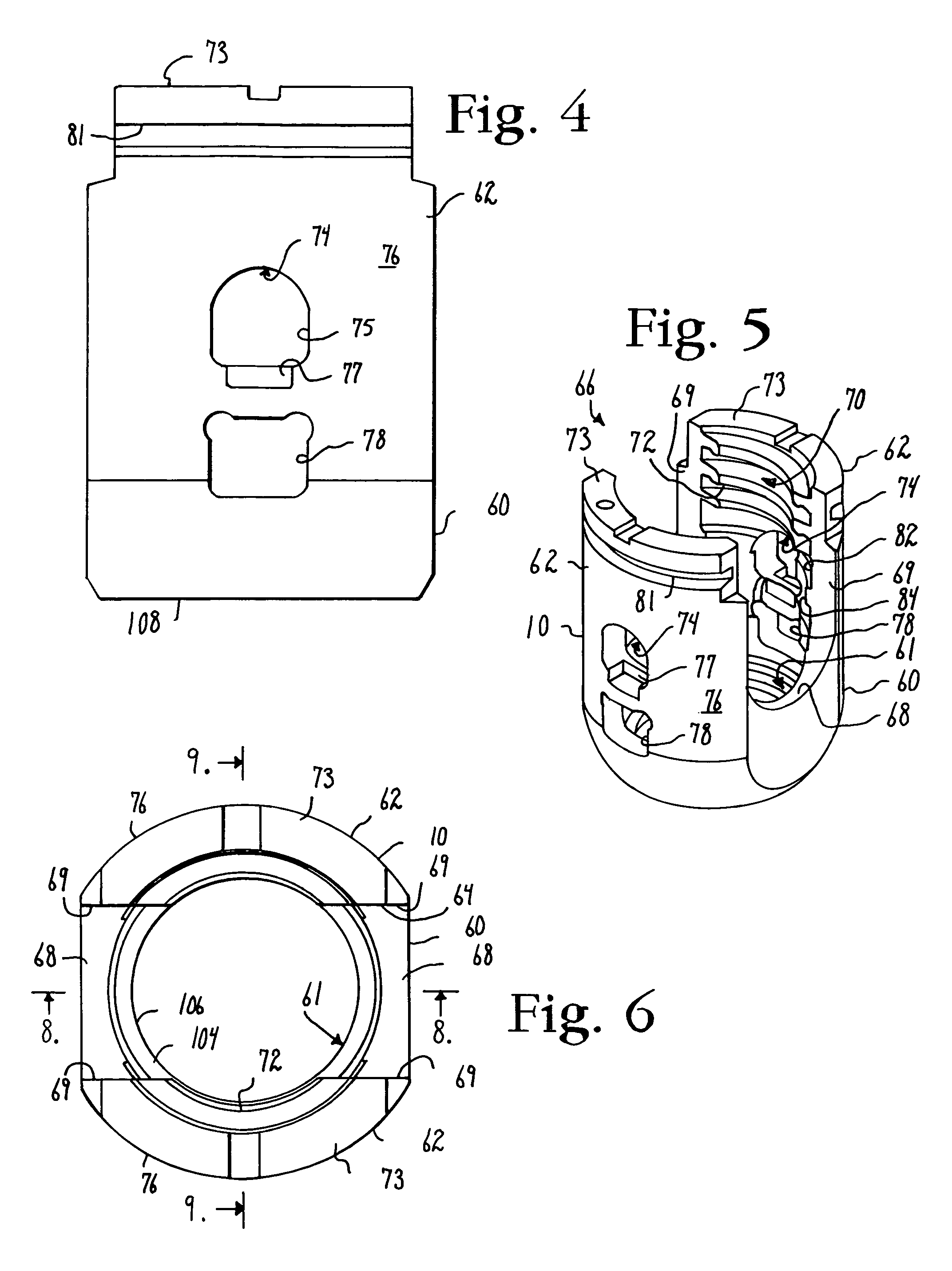
[0058]With reference to FIGS. 1-39 the reference number 1 generally represents a polyaxial bone screw apparatus or assembly according to the prese...
PUM
Abstract
A polyaxial bone screw assembly includes a threaded shank body having an integral upper portion receivable in an integral receiver, the receiver having an upper channel for receiving a longitudinal connecting member and a lower cavity cooperating with a lower opening. The receiver can have crimp tabs, but is devoid of spring tabs and collet-like flexible structures. A down-loadable compression insert (some with lock and release feature), a down-loadable friction fit split retaining ring having super structure for temporary friction fit with an up-loadable shank upper portion cooperate to provide for pop- or snap-on assembly of the shank with the receiver either prior to or after implantation of the shank into a vertebra. The shank and receiver once assembled cannot be disassembled.
Description
CROSS-REFERENCE TO RELATED APPLICATIONS[0001]This application claims the benefit of U.S. Provisional Patent Application Ser. No. 61 / 455,482 filed Oct. 21, 2010 that is incorporated by reference herein. This application is also a continuation-in-part of U.S. patent application Ser. No. 12 / 924,802 filed Oct. 5, 2010 that claims the benefit of the following U.S. Provisional Patent Application Ser. Nos.: 61 / 278,240, filed Oct. 5, 2009; 61 / 336,911, filed Jan. 28, 2010; 61 / 343,737 filed May 3, 2010; 61 / 395,564 filed May 14,2010; 61 / 395,752 filed May 17, 2010; 61 / 396,390 filed May 26, 2010; 61 / 398,807 filed Jul. 1, 2010; 61 / 400,504 filed Jul. 29, 2010; 61 / 402,959 filed Sep. 8, 2010; 61 / 403,696 filed Sep. 20, 2010; and 61 / 403,915 filed Sep. 23, 2010, all of which are incorporated by reference herein. This application is also a continuation-in-part of U.S. patent application Ser. No. 12 / 802,849 filed Jun. 15, 2010 that claims the benefit of U.S. Provisional Patent Application Ser. No. 61 / 268...
Claims
Application Information
Patent Timeline
Application Date:The date an application was filed.
Publication Date:The date a patent or application was officially published.
First Publication Date:The earliest publication date of a patent with the same application number.
Issue Date:Publication date of the patent grant document.
PCT Entry Date:The Entry date of PCT National Phase.
Estimated Expiry Date:The statutory expiry date of a patent right according to the Patent Law, and it is the longest term of protection that the patent right can achieve without the termination of the patent right due to other reasons(Term extension factor has been taken into account ).
Invalid Date:Actual expiry date is based on effective date or publication date of legal transaction data of invalid patent.