Printing apparatus and printing method

a printing head and printing apparatus technology, applied in the direction of printing, other printing apparatus, etc., can solve the problems of uneven feeding of recording medium to the print head, uneven feeding of recording medium, and uneven printing on recording medium, etc., to achieve stably feeding, stably performing, and stably performing

Active Publication Date: 2015-03-24
SEIKO EPSON CORP
View PDF5 Cites 1 Cited by
  • Summary
  • Abstract
  • Description
  • Claims
  • Application Information

AI Technical Summary

Benefits of technology

[0006]An advantage of some aspects of the invention is to provide a technique in which a recording medium can be smoothly displaced according to displacement of a rotating shaft in an axial direction and a position of the recording medium that is fed to a print head can be appropriately controlled in a configuration in which a support member that supports the recording medium subjected to a front surface modifying process is provided between the rotating shaft that feeds the recording medium and the print head.
[0009]In the printing apparatus and the printing method configured as above, the support member that supports the recording medium subjected to the front surface modifying process between the rotating shaft and the print head is displaced according to displacement of the rotating shaft that feeds the recording medium. Accordingly, since the support member is also displaced if the rotating shaft is displaced, interruption by the support member of displacement of the recording medium accompanied by the displacement of the rotating shaft can be suppressed. As a result, it is possible to appropriately control a position of the recording medium that is fed to the print head by smoothly displacing the recording medium according to the displacement of the rotating shaft in the axial direction.
[0010]At this point, the printing apparatus may be configured so that the process execution unit is displaced according to the displacement of the support member. That is, if the recording medium is displaced according to the displacement of the support member, a positional relationship between the process execution unit and the recording medium could be changed so the front surface modifying process by the process execution unit is affected. In contrast, if the process execution unit is displaced according to the displacement of the support unit, it is possible to suppress the change in the positional relationship between the process execution unit and the recording medium and stably perform the front surface modifying process.
[0012]In addition, the printing apparatus may further include a nip portion that nips the recording medium with a pair of rollers disposed between the rotating shaft and the print head so that the support member supports the recording medium between the rotating shaft and the nip portion. In a configuration in which the recording medium is nipped by the nip portion between the rotating shaft and the print head in this manner, the position of the recording medium from the nip portion to the rotating shaft is adjusted according to the displacement of the rotating shaft, and the change in the position of the recording medium from the nip portion to the print head is suppressed by nipping so that the feeding of the recording medium to the print head can be stably performed. That is, the recording medium of which the position is adjusted until the recording medium reaches the nip portion can be stably fed from the nip portion to the print head. Further, the support member provided between the rotating shaft and the nip portion in order to support the recording medium subjected to the front surface modifying process is displaced according to the displacement of the rotating shaft. Therefore, the position of the recording medium is appropriately adjusted until the recording medium reaches the nip portion without being interrupted by the support member and further the recording medium can be stably fed from the nip portion to the print head. As a result, the position of the recording medium that is fed to the print head can be controlled more appropriately.
[0013]Alternatively, the printing apparatus may further include a drive roller that supports the recording medium between the rotating shaft and the print head and feeds the recording medium to the print head, so that the support member supports the recording medium between the rotating shaft and the drive roller. In a configuration in which the drive roller supports the recording medium between the rotating shaft and the print head and feeds the recording medium to the print head in this manner, the position of the recording medium from the drive roller to the rotating shaft is adjusted according to the displacement of the rotating shaft and the feeding of the recording medium to the print head can be stably performed by driving the drive roller from the drive roller to the print head. That is, the recording medium of which the position is adjusted until the recording medium reaches the drive roller can be stably fed from the drive roller to the print head. Further, the support member provided between the rotating shaft and the drive roller in order to support the recording medium subjected to the front surface modifying process is displaced according to the displacement of the rotating shaft. Therefore, the position of the recording medium is appropriately adjusted until the recording medium reaches the drive roller without being interrupted by the support member, and also the recording medium can be stably fed from the drive roller to the print head. As a result, the position of the recording medium that is fed to the print head can be controlled more appropriately.
[0014]Further, the printing apparatus may further include a detection unit that detects a position of the recording medium in the axial direction so that the displacement amount of the rotating shaft in the axial direction is controlled based on a detection result of the detection unit. According to the configuration, the position of the recording medium can be adjusted with high accuracy so that the position of the recording medium that is fed to the print head can be controlled appropriately.

Problems solved by technology

However, if a recording medium is fed to a print head (ink ejecting head) using a mechanism such as the paper feeding unit that feeds the recording medium by rotating a rotating shaft that supports the recording medium, printing is not appropriately performed on the recording medium since the recording medium may be fed to the print head in a state where position deviation of the recording medium occurs in an axial direction of the rotating shaft.
However, as disclosed in JP-A-2012-200905, there is a concern that if a support member that supports the recording medium subjected to the front surface modifying process is provided between the rotating shaft and the print head, the recording medium is interrupted by friction force working between the support member and the recording medium so that the recording medium is not smoothly displaced according to the displacement of the rotating shaft and the position of the recording medium that is fed to the print head is not appropriately adjusted.

Method used


Image

  • Printing apparatus and printing method
  • Printing apparatus and printing method
  • Printing apparatus and printing method

Examples


Embodiment Construction

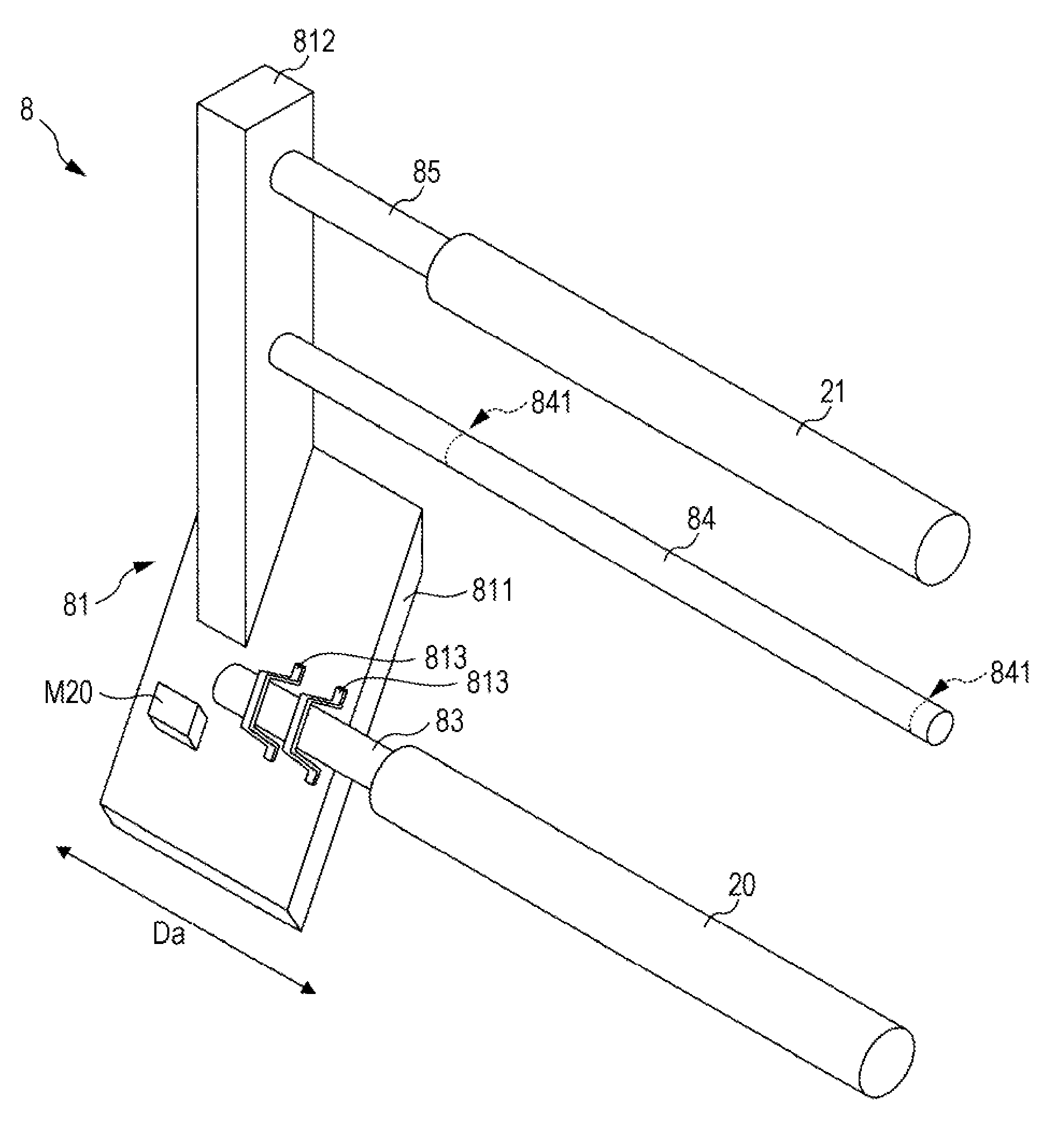
[0022]FIG. 1 is a front view schematically illustrating an example of an inside structure of a printer to which the invention can be applied. As illustrated in FIG. 1, in a printer 1, one sheet S (web) of which both ends are wound around a feeding shaft 20 and a winding shaft 40 in a roll shape is stretched between the feeding shaft 20 and the winding shaft 40, and the sheet S is transported from the feeding shaft 20 to the winding shaft 40 along a transportation path Pc that stretches in this manner. In other words, a feed roller R20 and a winding roller R40 are formed such that both ends of the sheet S in the transportation path Pc are wound in a roll shape. Therefore, the sheet S is transported from the feed roller R20 supported by the feeding shaft 20 to the winding roller R40 supported by the winding shaft 40 in a roll-to-roll manner.

[0023]Further, in the printer 1, an image is recorded on the sheet S transported along the transportation path Pc. The kind of sheet S is broadly ...


PUM


Abstract

A printing apparatus includes a rotating shaft that is displaceable in an axial direction and feeds a recording medium by rotating, a print head that prints on the recording medium that is fed from the rotating shaft, a support member that supports the recording medium between the rotating shaft and the print head, a process execution unit that performs a front surface modifying process on the recording medium supported by the support member, and a displacement mechanism that displaces the support member according to displacement of the rotating shaft.

Description

BACKGROUND[0001]1. Technical Field[0002]The present invention relates to a printing apparatus and a printing method for printing on a recording medium by a print head by feeding the recording medium to the print head using a rotating shaft that feeds the recording medium by rotating so that a position of the recording medium that is fed to the print head is adjusted by displacing the rotating shaft in an axial direction.[0003]2. Related Art[0004]An apparatus for printing by an ink ejecting head on a recording medium by feeding the recording medium wound in a roll shape from a paper feeding unit to the ink ejecting head is illustrated in FIG. 6 of JP-A-2012-200905. Further, a corona discharging device that faces a counter electrode disposed between the paper feeding unit and the ink ejecting head is provided in the apparatus for printing according to JP-A-2012-200905. In addition, the corona discharging device performs a corona process which is a kind of front surface modifying proce...

Claims


Application Information

Patent Timeline
Patent Type & Authority Patents(United States)
IPC IPC(8): B41J29/393B41J11/00B41J13/00B41J15/04
CPCB41J13/0009B41J11/0015B41J15/04B41J15/046
Inventor OSHIMA, TOSHIAKI
Owner SEIKO EPSON CORP
Why Eureka
Try Eureka