Camera module

a technology of camera module and holder, applied in the field of camera module, can solve problems such as damage to the holder, and achieve the effect of reducing the attraction force or repelling force and controlling the smooth displacement of the holder

Inactive Publication Date: 2007-09-20
MITSUMI ELECTRIC CO LTD
View PDF4 Cites 13 Cited by
  • Summary
  • Abstract
  • Description
  • Claims
  • Application Information

AI Technical Summary

Benefits of technology

[0013]With this structure, it is possible to reduce the attraction force or repelling force exerted between the second magnetic member and the second portion of the yoke to such an exte...

Problems solved by technology

Therefore, the conventional camera module involves a problem in that when an ...

Method used


Image

  • Camera module
  • Camera module
  • Camera module

Examples


Embodiment Construction

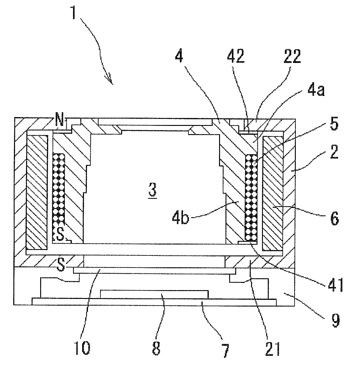
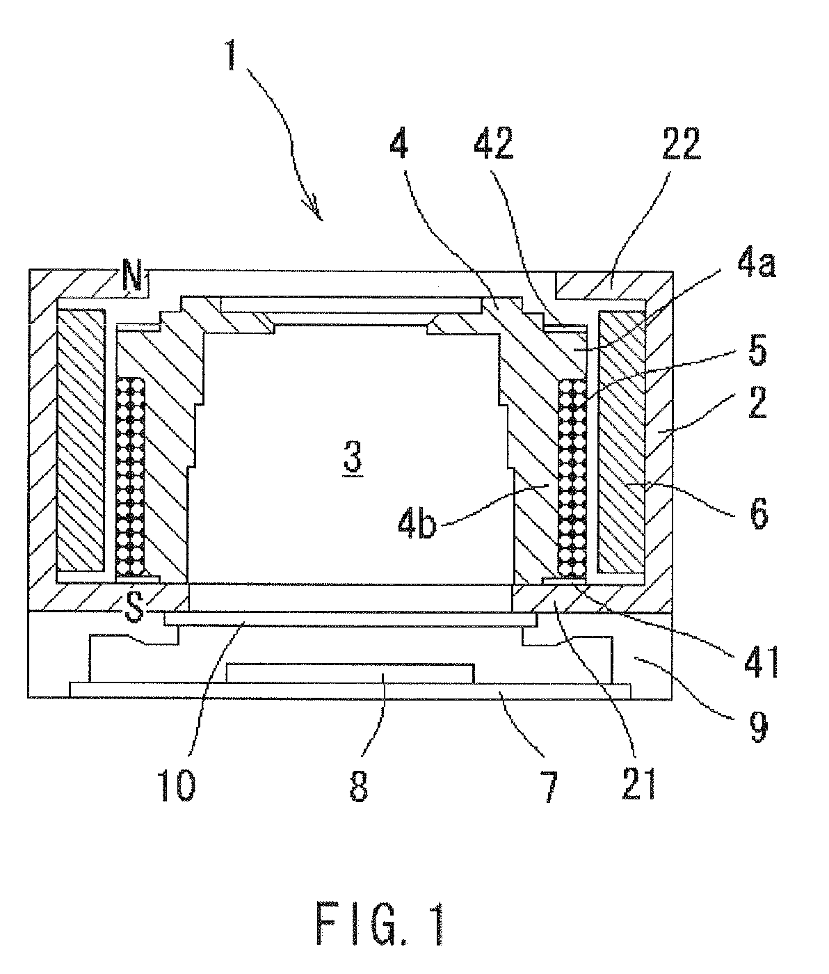
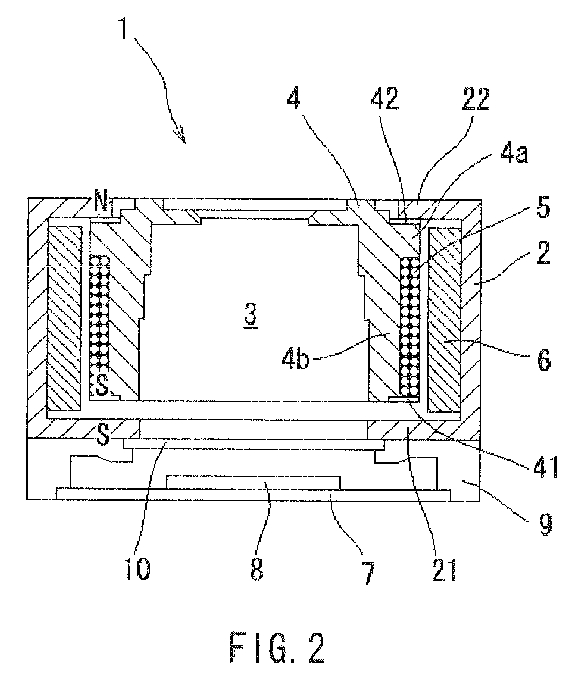
[0021]A camera module according to an embodiment of the present invention will be described below with reference to FIGS. 1 to 4. FIGS. 1 to 4 are cross sectional views of the camera module 1 of the embodiment according to the present invention, wherein FIG. 1 is shows a camera module 1 in a normal photographing mode and FIG. 3 shows a camera module 1 in a macro photographing mode. In this regard, it is to be noted that in this specification the terms “upper” or “top” and “lower” or “bottom” are used to denote the direction where a second portion 22 of a yoke 2 is located and the direction where a substrate 7 is located, respectively.

[0022]The camera module 1 is composed from a housing; a lens unit 3 having at least one lens which constitutes an optical system of the camera module 1; a holder 4 which houses the lens unit 3 and is displaceable between a first position and a second position along an optical axis direction of the lens unit 3; a first magnetic member 41 provided on the ...


PUM


Abstract

A camera module having a macro switching function which can be switched between a normal photographing and a macro photographing is provided. The camera module includes a housing; a lens unit having at least one leans; a lens holder which houses the lens unit therein and is displaceable between a first position and a second position along an optical axis direction of the lens unit; a first magnetic member provided on the holder at the side of the first position; a second magnetic member provided on the holder at the side of the second position; a coil wound around the holder and provided in a close vicinity of the first magnetic member; a yoke which constitutes a part of or an entire of the housing, the yoke having a first portion provided at a position that faces the first magnetic member and a second portion provided at a position that faces the second magnetic member; a magnet provided on the yoke in a state that a space is left between the coil and the magnet; and an image pick-up device provided below the lens unit.

Description

BACKGROUND OF THE INVENTION[0001]1. Field of the Invention[0002]The present invention relates to a camera module, and more specifically to a camera module having a macro switching function which is used in relatively small-sized electronic apparatuses such as digital cameras, camera-equipped cellular phones and the like.[0003]2. Description of the Prior Art[0004]A camera module having a macro switching function is used in small-sized digital cameras, camera-equipped cellular phones and the like. The macro switching function is a function of the camera module that makes it possible to switch a photographing mode of the camera module between a normal photographing mode and a macro photographing mode. In more detail, such a camera module includes a hand-manipulated lever, and a holder having at least one lens which constitutes an optical system of the camera module. The camera module is configured so that the holder can be mechanically displaced in a direction of an optical axis of the...

Claims


Application Information

Patent Timeline
IPC IPC(8): H04N5/225H01L27/00G02B7/04G02B7/105H02K33/18H04N5/335
CPCG02B7/105H04N5/2257H04N5/2254G03B17/12H04N23/57H04N23/55
Inventor HONMA, TOSHIHIKO
Owner MITSUMI ELECTRIC CO LTD
Why Eureka
Try Eureka