Modular intraocular lens designs, tools and methods

a module and intraocular lens technology, applied in the field of intraocular lenses, can solve the problems of deteriorating vision, needing adjustment, and suboptimal optical results, and achieve the effects of preventing capsular rupture, minimizing or avoiding anterior-posterior forces, and reducing vision deterioration

Active Publication Date: 2018-09-25
ALCON INC +1
View PDF240 Cites 22 Cited by
  • Summary
  • Abstract
  • Description
  • Claims
  • Application Information

AI Technical Summary

Benefits of technology

[0012]The primary component may have haptics (e.g., projections) extending therefrom for centration in the capsular bag, and the secondary component may exclude haptics, relying instead on attachment to the primary component for stability. The secondary component may reside radially inside the perimeter of the capsulorhexis, thereby negating the need to disturb the capsular bag to manipulate or exchange the secondary component. The attachment between the primary component and the secondary component may reside radially inside the perimeter of the capsulorhexis and radially outside the field of view to avoid interference with light transmission. Alternatively or in addition, the attachment may comprise a small fraction of the perimeter (e.g., less than 20%) of the secondary component to minimize the potential for interference in light transmission.
[0013]The primary component may have an anterior surface that is in intimate contact with a posterior surface of the secondary component to prevent fluid ingress, tissue ingrowth, and / or optical interference. The secondary component may be removably secured to the primary component by mechanical attachment and / or chemical attraction, for example. Mechanical attachment may be facilitated by mating or interlocking geometries corresponding to each of the primary and the secondary components. Such geometries may be pre-formed by molding or cutting, for example, or formed in-situ by laser etching, for example. Chemical attraction may be facilitated by using similar materials with a smooth surface finish activated by a surface treatment, for example. In some instances, it may be desirable to reduce chemical attraction and rely more on mechanical attachment for stability. In this case, the primary and secondary components may be formed of dissimilar materials or otherwise have adjacent surfaces that do not have a chemical attraction.
[0017]The surgical cutting tools and removal methods may apply balanced forces and / or torques on the secondary lens to minimize movement thereof during cutting. This minimizes or avoids anterior-posterior forces on the capsular bag and prevents capsular rupture. The removal methods may avoid flexing the secondary lens (“tenting”) and / or rotating the secondary lens in the anterior-posterior direction, again to avoid trauma to the capsular bag. The cut may be a “clean cut” so as to avoid generating small fragments, debris or jagged edges.

Problems solved by technology

When age or disease causes the lens to become less transparent (e.g., cloudy), vision deteriorates because of the diminished light, which can be transmitted to the retina.
After cataract surgery to implant an IOL, the optical result may be suboptimal or may need adjustment over time.
In general, manipulation of the capsular bag to remove an IOL risks damage to the capsular bag including posterior rupture.
This risk increases over time as the capsular bag collapses around the IOL and tissue ingrowth surrounds the haptics of the IOL.
While this design may have the advantage of avoiding manipulation of the capsular bag, its primary disadvantage is engaging the ciliary sulcus.
Such injury may result in complications such as bleeding, inflammation and hyphema.
As stated previously, manipulation of the capsular bag may be undesirable given the risks associated therewith.
Therefore, while such lens systems may avoid the potential for injury to the ciliary sulcus by implanting both the primary lens and the secondary lens in the capsular bag, these systems do not avoid manipulation of the capsular bag to attach the secondary lens.

Method used


Image

  • Modular intraocular lens designs, tools and methods
  • Modular intraocular lens designs, tools and methods
  • Modular intraocular lens designs, tools and methods

Examples


Embodiment Construction

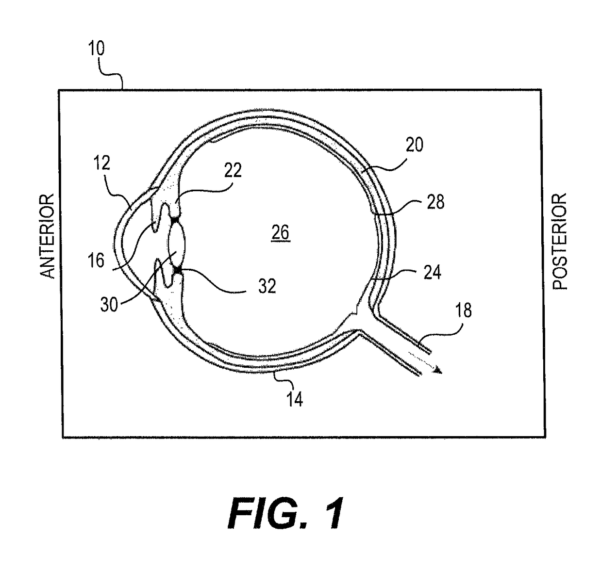
[0051]With reference to FIG. 1, the human eye 10 is shown in cross section. The eye 10 has been described as an organ that reacts to light for several purposes. As a conscious sense organ, the eye allows vision. Rod and cone cells in the retina 24 allow conscious light perception and vision including color differentiation and the perception of depth. In addition, the human eye's non-image-forming photosensitive ganglion cells in the retina 24 receive light signals which affect adjustment of the size of the pupil, regulation and suppression of the hormone melatonin, and entrainment of the body clock.

[0052]The eye 10 is not properly a sphere; rather it is a fused two-piece unit. The smaller frontal unit, more curved, called the cornea 12 is linked to the larger unit called the sclera 14. The corneal segment 12 is typically about 8 mm (0.3 in) in radius. The sclera 14 constitutes the remaining five-sixths; its radius is typically about 12 mm. The cornea 12 and sclera 14 are connected b...


PUM


Abstract

Modular IOL removal systems and methods that cut an optic portion of an intraocular in a single motion such to facilitate removal of the optic portion from an eye through an incision, for example a corneal incision, without increasing the size of the corneal incision. Various cutting tools having one or more blades may be utilized. The cut intraocular lens may have one continuous cut or be cut into multiple smaller pieces. The single cutting step may apply balanced forces and torque to avoid damaging the surrounding eye anatomy, reducing the risk of trauma.

Description

CROSS-REFERENCE TO RELATED APPLICATIONS[0001]This application claims the benefits under 35 U.S.C. § 119(e) of priority to U.S. Provisional Patent Application No. 61 / 941,167, filed Feb. 18, 2014, entitled “MODULAR INTRAOCULAR LENS DESIGNS, TOOLS AND METHODS,” the entirety of which is incorporated herein by reference. This application is related to U.S. patent application Ser. No. 13 / 969,115, filed Aug. 16, 2013, entitled “MODULAR INTRAOCULAR LENS DESIGNS & METHODS,” which claims the benefits under 35 U.S.C. § 119(e) of priority to U.S. Provisional Patent Application No. 61 / 830,491, filed Jun. 3, 2013, entitled “MODULAR INTRAOCULAR LENS DESIGNS AND METHODS,” each of which is incorporated herein by reference. This application also is related to U.S. patent application Ser. No. 13 / 748,207, filed Jan. 23, 2013, entitled “MODULAR INTRAOCULAR LENS DESIGNS & METHODS,” which claims the benefits under 35 U.S.C. § 119(e) of priority of U.S. Provisional Patent Application No. 61 / 589,981, filed ...

Claims


Application Information

Patent Timeline
Patent Type & Authority Patents(United States)
IPC IPC(8): A61F9/007A61F2/16A61F9/008
CPCA61F2/1648A61F9/00754A61F9/00834A61F2009/0087A61F2/1664A61F9/00736A61F2/1662
Inventor KAHOOK, MALIK Y.SUSSMAN, GLENNMCLEAN, PAULSCHIEBER, ANDREW THOMAS
Owner ALCON INC
Why Eureka
Try Eureka