Structure of inflatable packaging device

a packaging device and packaging technology, applied in packaging, sacks, flexible containers, etc., can solve the problems of preventing requiring expensive molds for their production, and not being able to recycle styrofoam, so as to prevent the rupture of fluid containers, the effect of reducing the shock or vibration of a produ

Active Publication Date: 2015-05-12
AIR PAQ
View PDF10 Cites 5 Cited by
  • Summary
  • Abstract
  • Description
  • Claims
  • Application Information

AI Technical Summary

Benefits of technology

[0012]It is, therefore, an aspect of embodiments of the present invention to provide a structure of a packaging device for packing a product that can minimize a shock or vibration and protect the product.
[0014]It is a further aspect of embodiments of the present invention to provide a structure of a packaging device that has improved durability to prevent rupture of the packaging device caused by a pointed corner of a product.
[0023]According to various embodiments of the present invention, the packaging device can minimize the shocks or vibrations to a product when the product is dropped or collided. The packaging device includes the plurality of fluid containers each having a plurality of cells connected in series. After being inflated, for example, by compressed air, the lining formed by the uninflated section of the packaging device. The uninflated section of the packaging device acts as a lining that holds a product to be protected, while the lining helps prevent rupture of the fluid containers by preventing direct contact of the product to the inflated section.

Problems solved by technology

For example, recycling the styrofoam is not possible, soot is produced when it burns, a flake or chip comes off when it is snagged because of it's brittleness, an expensive mold is needed for its production, and a relatively large warehouse is necessary to store it.
Third, the air-packing device does not produce a chip or dust which may have adverse effects on precision products.
In case the product to be protected has a pointed end, the possibility exists that the air-packing device may be ruptured by it.

Method used


Image

  • Structure of inflatable packaging device
  • Structure of inflatable packaging device
  • Structure of inflatable packaging device

Examples


Embodiment Construction

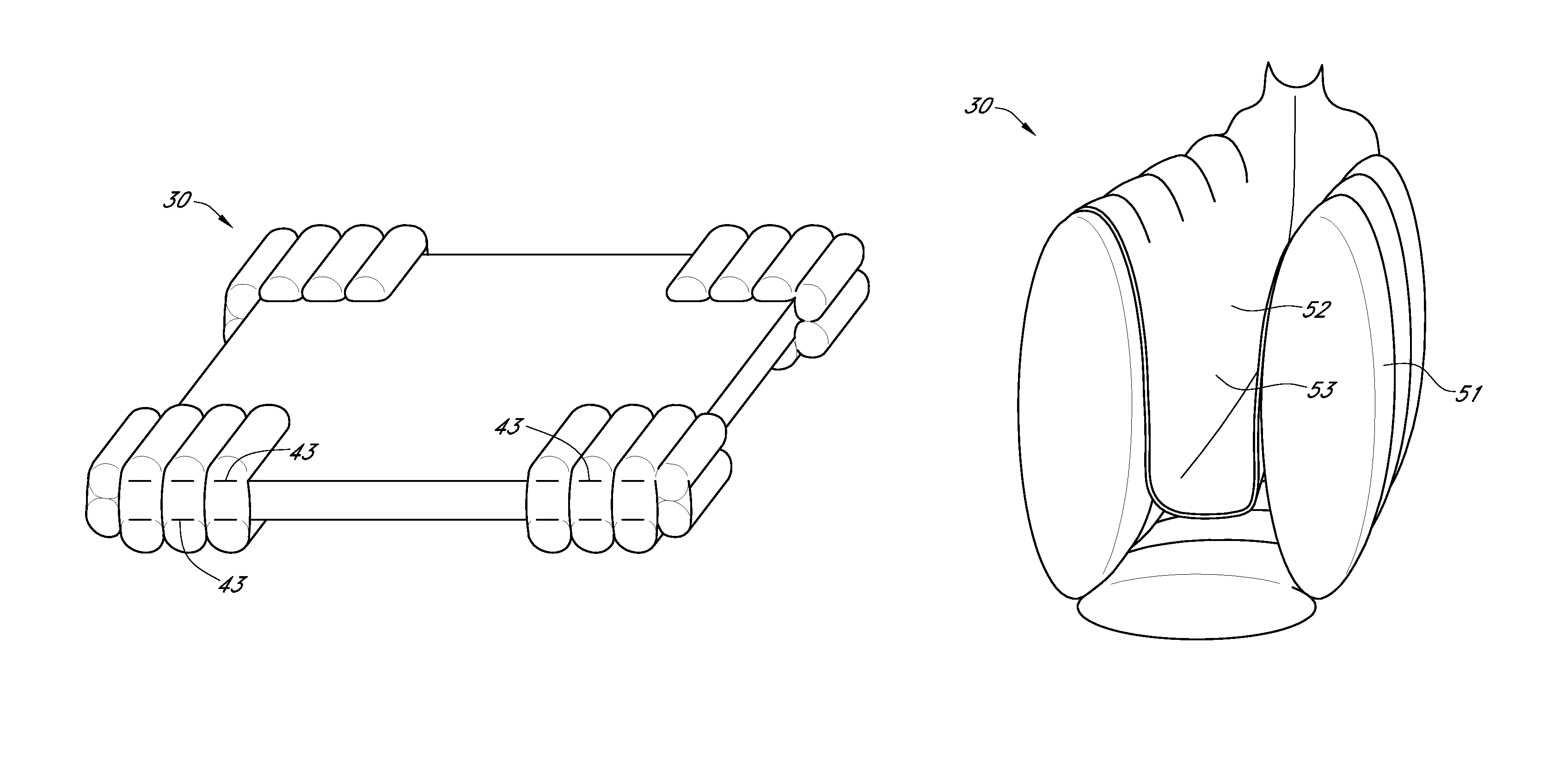
[0037]The packing device according to various embodiments of the present invention will be described in more detail with reference to the accompanying drawings. It should be noted that although various embodiments are described for the case of using an air for inflating the packing device for an illustration purpose, other fluids such as other types of gas or liquid can also be used. The packing device is typically used in a container box to pack a product during the distribution channel of the product.

[0038]The packing device according to an embodiment of the present invention is especially useful for packing products which are sensitive to shock or vibration such as hard disk drives, personal computers, DVD drivers, bottles, glassware, ceramic ware, music instruments, paintings, antiques, etc. The packaging device reliably holds the product within a lining area of the packaging device to secure the product to be protected. As a lining in the lining area prevents the product to dir...


PUM


Abstract

A packaging device includes first and second thermoplastic films superposed with each other, wherein predetermined portions of the thermoplastic films are bonded creating a plurality of fluid containers, a plurality of check valves each connected to a corresponding fluid container, a fluid passage in a first direction connected to the check valves, and a second border between an inflated section including the plurality of fluid containers and an uninflated section, wherein the first and second thermoplastic films are folded and two side edges of the films are bonded and a first portion of a first border connecting the inflated section to a second section is folded and an overlapped portion of the first portion is bonded leaving a remaining portion of the first border unbonded wherein the uninflated section forms a loop, and wherein the uninflated section forming the loop is folded into the inflated section to form a lining.

Description

CROSS-REFERENCE TO RELATED APPLICATIONS[0001]The present application hereby incorporates by reference the entire technical disclosures of U.S. Pat. Nos. 7,422,108 and 7,938,264.BACKGROUND OF THE INVENTION[0002]1. Field of the Invention[0003]Embodiments of this invention relate to a structure of a packaging device for use as packing material, and more particularly, to a pocket corner pack device and a pocket end cap device for achieving an improved shock absorbing capability to protect a product from a shock or impact characterized as having an inflated portion and an uninflated lining portion.[0004]2. Description of the Related Art[0005]In product distribution channels such as product shipping, a styrofoam packing material has been used for a long time for packing commodity and industrial products. Although the styrofoam package material has a good thermal insulation performance and a light weight, it has also various disadvantages. For example, recycling the styrofoam is not possib...

Claims


Application Information

Patent Timeline
Patent Type & Authority Patents(United States)
IPC IPC(8): B65D81/02B65D30/00B65D81/05
CPCB65D81/052B65D81/057B65D81/058
Inventor YOSHIFUSA, KARK K
Owner AIR PAQ
Why Eureka
Try Eureka