C-arm computerized tomography system

a computerized tomography and c-arm technology, applied in the field of c-arm fluoroscopic image system, can solve the problems of c-arm motion, expensive equipment, and new equipment expenditure, and achieve the effect of reducing the motion effect of the c-arm

Active Publication Date: 2015-06-02
MAZOR ROBOTICS
View PDF41 Cites 188 Cited by
  • Summary
  • Abstract
  • Description
  • Claims
  • Application Information

AI Technical Summary

Benefits of technology

[0019]In accordance with still another preferred embodiment of the present invention, the image processing unit may preferably comprise an image deblurring module for reducing the effect of motion of the C-arm. In any of the above described systems, the C-arm may be adapted to be moved manually, or to be motor driven. Additionally, the target may preferably be affixed to the subject or to a platform on which the subject is lying, such as the OP bed.
[0023]In accordance with still another preferred embodiment of the present invention, the above mentioned method may preferably further comprise the step of processing the images in a deblurring module for reducing the effect of motion of the C-arm. In any of the above described methods, the step of applying a motion path to the C-arm may be performed manually or by means of a motor. Additionally, the target may preferably be affixed to the subject, or to a platform on which the subject is lying, such as the OR bed.

Problems solved by technology

Computerized Tomography (CT) is generally performed using a dedicated CT system, which is an expensive piece of equipment, found in limited numbers within the health care environment, and generally, because of its size and weight, in dedicated locations within the health care facility.
Although considerably less costly than a CT system, this system does involve the capital expenditure of the new equipment, or the cost of amending an existing C-arm fluoroscope by installation of the additional features required for its operation.

Method used


Image

  • C-arm computerized tomography system
  • C-arm computerized tomography system
  • C-arm computerized tomography system

Examples


Embodiment Construction

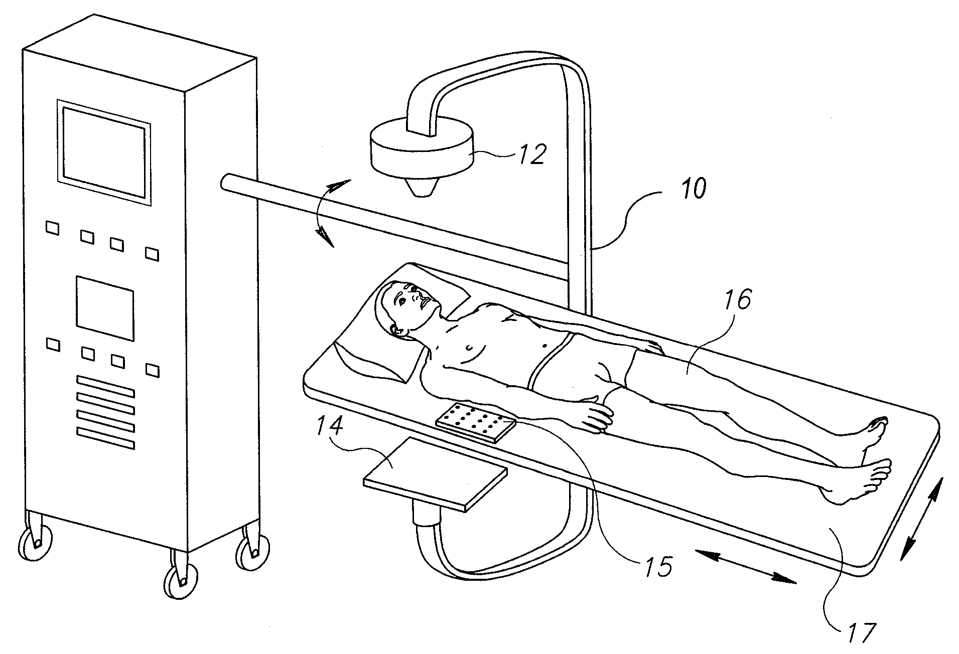
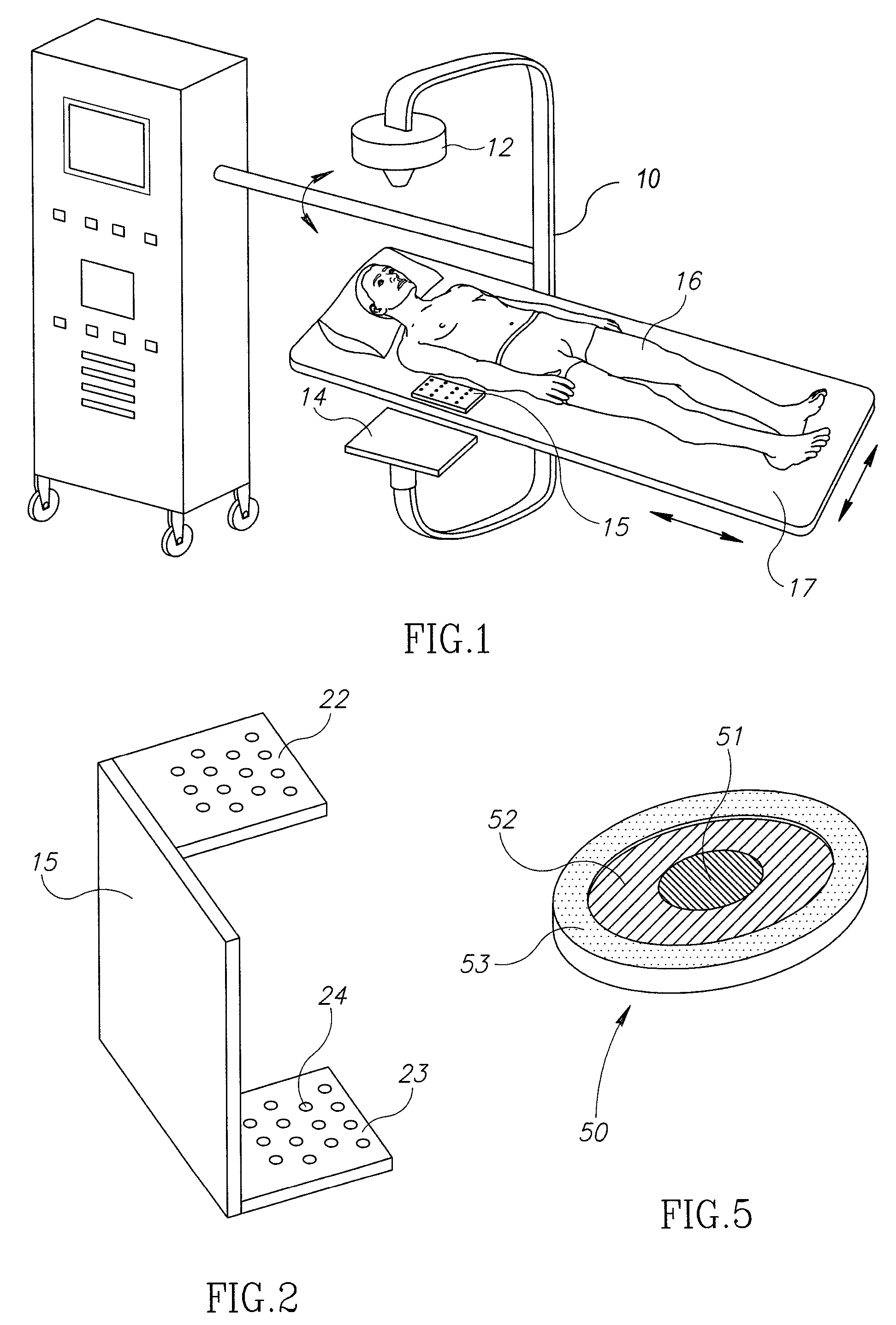
[0031]Reference is now made to FIG. 1, which illustrates schematically a C-arm system, constructed and operative according to a preferred embodiment of the present invention, which enables the generation of 3-dimensional CT-type information generally using the existing features of the C-arm, without the need for structural changes. The C-arm 10 has an X-ray source 12 on one end of its jaws, and a detector array 14 at the other end, for detecting the two-dimensional absorption image generated by passage of the X-rays through the subject 16 lying on the bed 17. The detector array preferably comprises an image intensifier coupled to a video camera, thus converting the incident photons into a video signal which dynamically shows the X-ray absorption shadow images.

[0032]A three dimensional target 15 containing X-ray opaque marker balls, is located in a fixed position relative to the subject, so that its image, or at least part of it, shows up in the video images generated by the system. ...


PUM


Abstract

A system and method for generating CT-type three dimensional imaging information from a conventional C-arm fluoroscope system. This enables the adaptation of widely used C-arm installations to provide CT-type information. The system uses a three dimensional target disposing in a fixed position relative to the subject, and obtains a sequence of video images of a region of interest of a subject while the C-arm is moved manually or by a scanning motor. Images from the video sequence are analyzed to determine the pose of the C-arm relative to the subject by analysis of the image patterns of the target. Images are selected from the video sequence according to predetermined criteria. A set of two-dimensional image data with associated positional data is obtained, which is used to reconstruct a three dimensional volumetric set of imaging data of the region of interest of the subject.

Description

CROSS REFERENCE TO PRIOR APPLICATIONS[0001]This is the U.S. National Phase application under 35 U.S.C. §371 of International Patent Application No. PCT / IL2007 / 001193, filed Sep. 25, 2007, and claims the benefit of U.S. Provisional Application No. 60 / 846,750, filed Sep. 25, 2006 and U.S. Provisional Application No. 60 / 907,874, filed Apr. 20, 2007, both of which are incorporated by reference herein. The International Application published in English on Apr. 3, 2008 as WO 2008 / 038283 under PCT Article 21(2).FIELD OF THE INVENTION[0002]The present invention relates to the field of CT imaging, especially as generated using a conventional C-arm fluoroscopic image system.BACKGROUND OF THE INVENTION[0003]Computerized Tomography (CT) is generally performed using a dedicated CT system, which is an expensive piece of equipment, found in limited numbers within the health care environment, and generally, because of its size and weight, in dedicated locations within the health care facility. It i...

Claims


Application Information

Patent Timeline
Patent Type & Authority Patents(United States)
IPC IPC(8): A61B6/00
CPCA61B6/4405A61B6/4441A61B6/583H05G1/02
Inventor RUBNER, JOSEPHZEHAVI, ELIKLEYMAN, LEONIDSHOHAM, MOSHE
Owner MAZOR ROBOTICS
Why Eureka
Try Eureka