Shift device for transmission

Active Publication Date: 2015-06-16
KAWASAKI MOTORS LTD
View PDF8 Cites 12 Cited by
  • Summary
  • Abstract
  • Description
  • Claims
  • Application Information

AI Technical Summary

Benefits of technology

[0010]The present invention has been devised in view of the above-mentioned problems. An object thereof is to provide a shift device in which an arrangement flexibil

Problems solved by technology

Further, the work of removing the coil spring 320 also takes time and effort.
Furt

Method used


Image

  • Shift device for transmission
  • Shift device for transmission
  • Shift device for transmission

Examples


Embodiment Construction

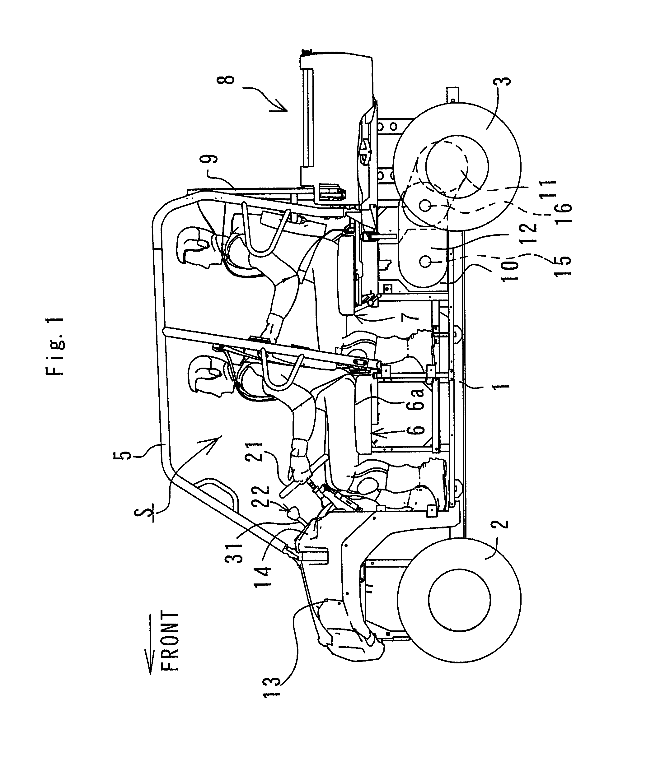
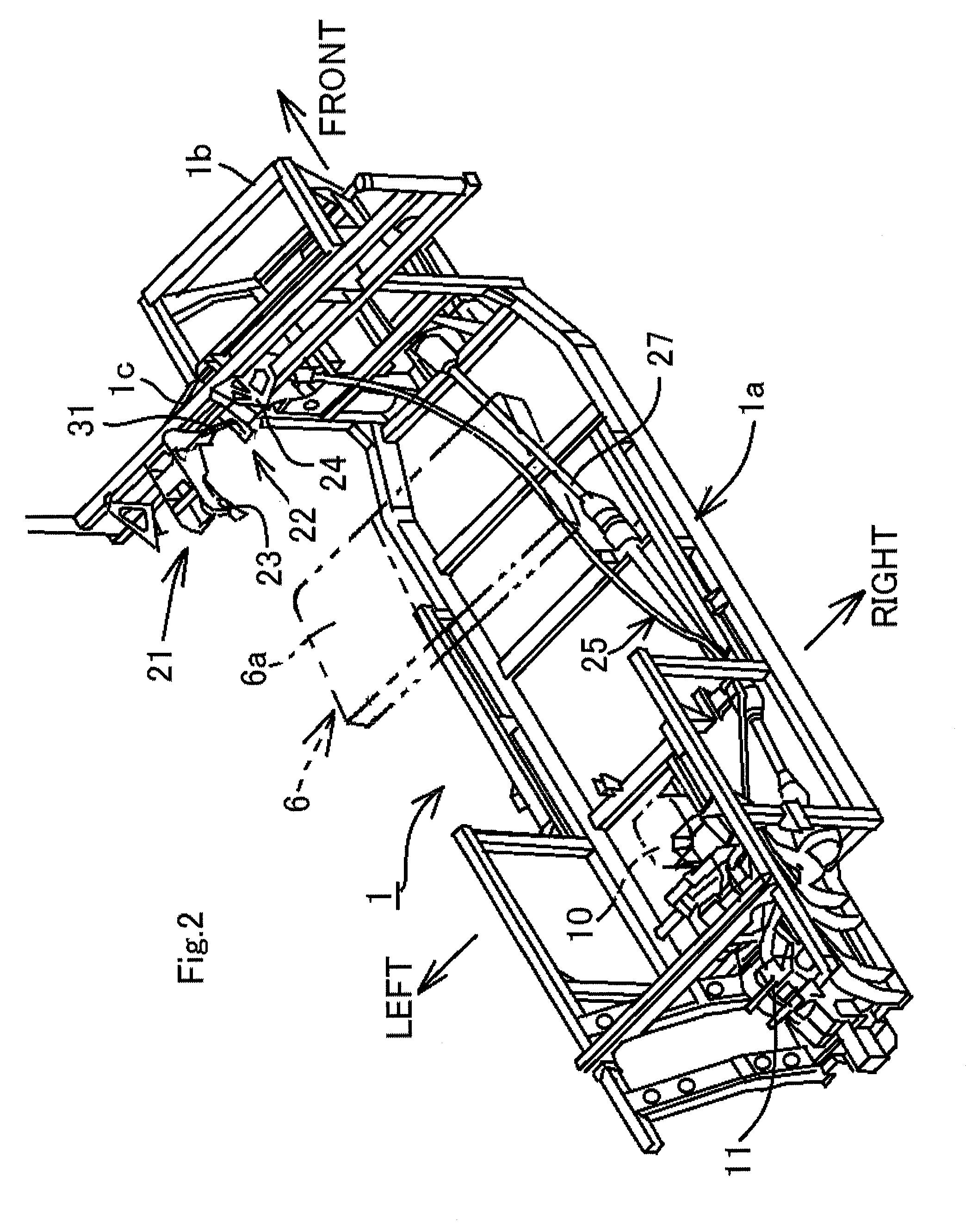
[0039]FIGS. 1 to 9 show a shift device according to the present invention and a utility vehicle including the shift device. Then, an embodiment of the present invention is described below with reference to these drawings. For convenience of description, a forward traveling direction of the utility vehicle will be described as a “front side” of the utility vehicle and respective components, and a left-and-right direction viewed from a driver will be described as a “left-and-right direction” of the utility vehicle and the respective components.

[0040]In FIG. 1, a pair of right and left front wheels 2 is provided in a front portion of a vehicle body frame 1 of the utility vehicle and a pair of right and left rear wheels 3 is provided in a rear portion of the vehicle body frame 1. A riding space S formed between the front wheels 2 and the rear wheels 3 is surrounded by a ROPS 5, where the ROPS 5 is an abbreviation of a rollover protective structure. A bench type front seat 6 is arranged ...


PUM


Abstract

The present invention is a shift device for switching a dog clutch mechanism in a transmission, comprising: a shift shaft capable of moving in an axial direction; a shift member capable of moving in the axial direction within a predetermined waiting stroke range; an elastic member holder for a waiting mechanism; and an elastic member provided in outside of the shift shaft in a radial direction so as to be compressed and expanded between the elastic member holder and the shift member, wherein the elastic member biases the shift member toward one side in the axial direction.

Description

BACKGROUND OF INVENTION[0001]1. Field of the Invention[0002]The present invention relates to a shift device for switching a dog clutch mechanism in a transmission.[0003]2. Description of the Prior Art[0004]FIG. 11 shows a shift device of a gear transmission described in JP Laid-open Publication No. 2006-082737. The shift device includes: a shift shaft 302, a shift fork 303 fixed to the shift shaft 302 and a shift sleeve 304 engaging with the shift fork 303. The shift shaft 302 is supported by a transmission case 301 so as to be movable in an axial directional of the shift shaft 302. A drive pin 308 of the shift fork 303 engages with an inner lever 307 fixed to the lower end portion of a lever shaft 306. The lever shaft 306 is free-rotatably supported by the transmission case 302. The lever shaft 306 is connected to a shift lever device through an outer lever 310 and a shift operation force transmission mechanism (not shown).[0005]A waiting mechanism includes a coil spring 320 fit on...

Claims


Application Information

Patent Timeline
IPC IPC(8): F16H59/04F16H63/30F16H3/08
CPCF16H63/30F16H3/08F16H2063/3076F16H2063/3089
Inventor ITOO, SEIJIHAMADA, AYUMIMORITA, TAISUKE
Owner KAWASAKI MOTORS LTD
Why Eureka
Try Eureka