
Hovering toy figure

a toy figure and hovering technology, applied in the field of remote control flying toys, can solve the problems of mechanical and awkward appearance of toys during flight, the arrangement of wings in these toy figures does not produce a realistic flight simulation of the actual figure, and the toy material is usually unstable and difficult to maneuver, so as to reduce the aerodynamic force, reduce the form and stiffness of the wing material, and minimize the effect of bouncing

Active Publication Date: 2015-07-07
TANOUS WORKS
View PDF26 Cites 9 Cited by
  • Summary
  • Abstract
  • Description
  • Claims
  • Application Information

AI Technical Summary

Benefits of technology

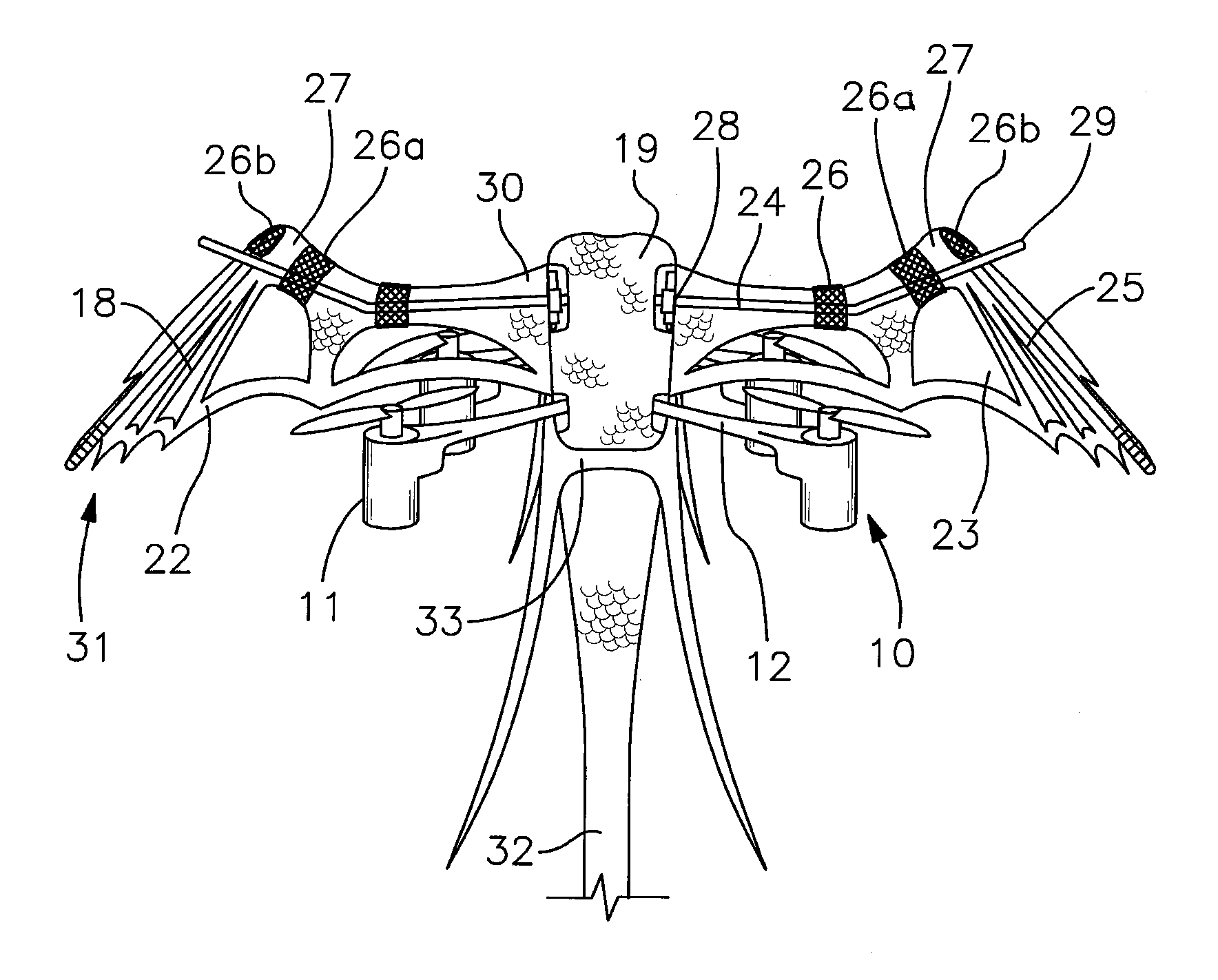
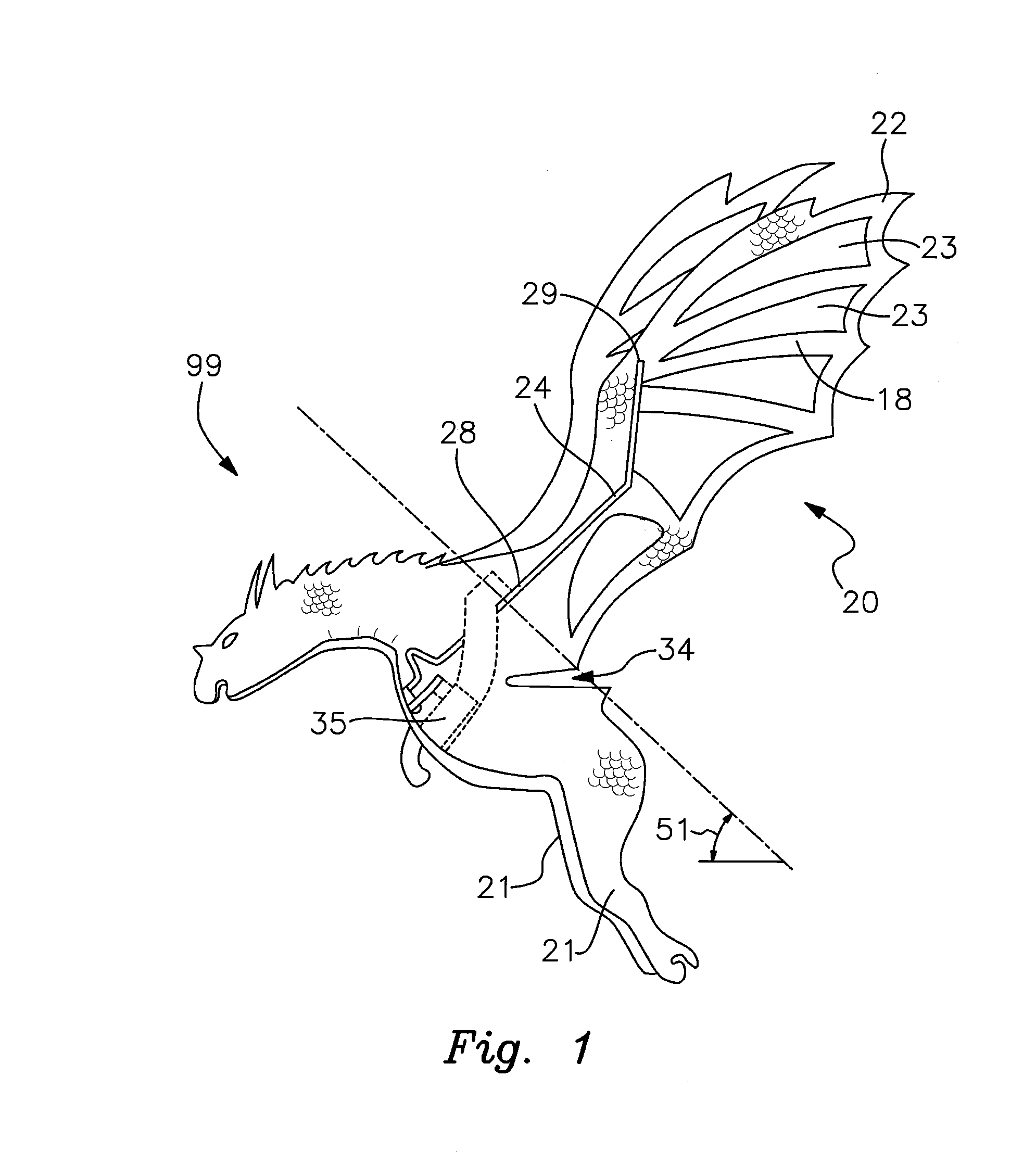
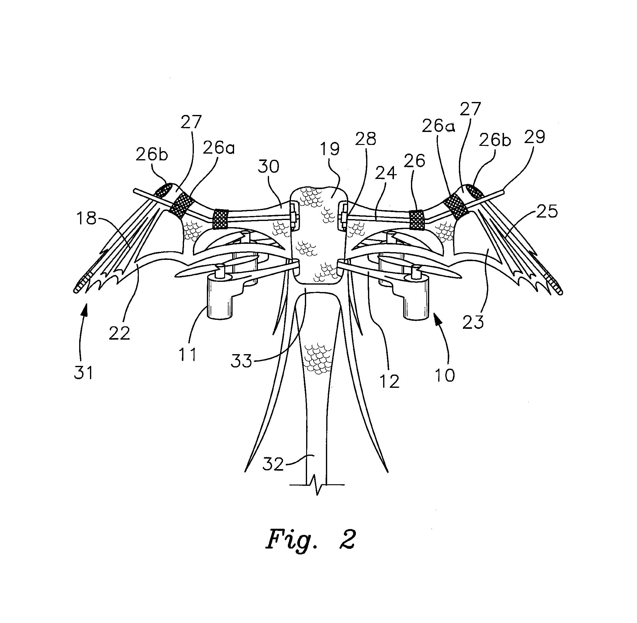
[0008]The winged body generally comprises one or more side panels and two or more wings. The wings are configured either with or without apertures that enable the passage of air through the wings. In effect, the apertures remove surface area from the wings, thus reducing the aerodynamic forces generated by the wings during the flapping motion. The wings comprise a first spine to provide form and stiffness to the wing material. The first spine has a base and a distal end, wherein the base connects to the wing actuation assembly, as described below.
[0009]In some embodiments, it is preferable for the wing to comprise a second spine, which simulates the second finger or third finger of a Chiropteran-style wing. The second spine is attached to the wing in proximity to the second finger or third finger of the wing. The first and second spines are oriented on the wing such that the spines cross tips in the proximity of the wrist of the wing, with the distal end of the first spine crossing above the tip of the second spine. The first spine and the second spine are separated to form a flex zone between the attachment means of the respective spines. On the upstroke of the wing, the wing actuation assembly lifts the first spine, and the wing bends at the flex zone such that the wing distal end droops as the wing is raised. At the top of the upstroke, the wing distal end snaps to an upright position due to its momentum, and the down stroke of the flapping cycle begins again. During the down stroke of the wing, the wing distal end straightens out, and the second spine abuts the crossing first spine such that the first and second spines provide stiffness across the flex zone along the full length of the wing. In this manner, when the wing droops on the upstroke and straightens on the down stroke, the action of the wing appears more realistic during flight of the toy figure.
[0010]The wing actuation assembly comprises the components necessary to actuate wing movement in a flapping motion. For example, in one embodiment the wing actuation assembly comprises a frame having a base, vertical struts, and a servo. The servo has a rotating arm, which is connected to a linking assembly. As the arm rotates, the motion of the arm drives the linking assembly up and down in a cyclical manner, which drives the wings up and down in the flapping movement. During flight, the flapping wings cause a “bouncing” effect, making the hovering toy figure appear to be life-like during flight. The bouncing effect becomes more pronounced when there are no wing apertures, or when such apertures are relatively small. The bouncing effect is minimized, or even eliminated, when the area of the apertures approaches that of the overall wing surface area. To further enhance the life-like appearance of the hovering toy figure, the wings pivot about an axis that is inclined at an angle ranging from about 15-degrees to about 75-degrees as measured from horizontal.

Problems solved by technology

These toys commonly rely on ornithopter-style flapping assemblies, and they are usually unstable and difficult to maneuver.
In addition, the arrangement of wings in these toy figures does not produce a realistic flight simulation of the actual figure.
Instead, these toys appear to be mechanical and awkward in appearance during flight.

Method used


Image

  • Hovering toy figure
  • Hovering toy figure
  • Hovering toy figure

Examples


Embodiment Construction

[0020]With reference to the drawings, the invention will now be described with regard to the best mode and the preferred embodiment. In general, the device is a remote-controlled, hovering toy figure in the shape of a winged bird, reptile, mammal, or mythical creature, wherein the flapping wings simulate flight of the figure. The embodiments disclosed herein are meant for illustration and not limitation of the invention. An ordinary practitioner will appreciate that it is possible to create many variations and combinations of the following embodiments without undue experimentation.

[0021]By way of example and not limitation, the following discussion will generally present the hovering toy FIG. 99 in the context of a dragon-shaped body. However, it will be appreciated that the hovering toy FIG. 99 may take the form of a variety of other creatures, such as bird, reptile, mammal, or mythical creature. As used herein, the terms “right,”“left,”“forward,”“rearward,”“top,”“bottom,” and the ...


PUM


Abstract

A remote controlled hovering toy figure having a propulsion system, a control system, a winged body, and a wing actuation assembly. The winged body is mounted to the propulsion system, which is controlled by the control system. The wing actuation assembly is mounted to the winged body, and the wing actuation assembly is powered by the control system. The wing actuation assembly drives the wings in an oscillating flapping motion. The wings comprise apertures permitting air to pass through the wing, thus reducing the aerodynamic effect of the flapping motion. In this manner, the wings produce a softened “bouncing” flight action, thus creating a realistic flight motion. In another embodiment, the propulsion system comprises one or more rotors in a coaxial arrangement, and a rotor mast housing in the shape of a rider riding the hovering toy figure.

Description

CROSS REFERENCE TO RELATED APPLICATIONS[0001]Pursuant to 35 U.S.C. §119(e), this application claims the benefit of U.S. Provisional Patent Application Ser. No. 61 / 823,861, filed on May 15, 2013, and the benefit of U.S. Provisional Patent Application Ser. No. 61 / 875,653, filed on Sep. 9, 2013, the entire contents of both of which are incorporated herein by this reference.BACKGROUND[0002]1. Field of the Invention[0003]The present invention relates generally to the field of remote controlled flying toys, and more particularly, to a hovering toy figure that simulates the flight of birds, insects, reptiles, mammals, and mythical creatures having wings that support flight in a flapping motion.[0004]2. Description of Related Art[0005]Past winged toy figures rely on rapidly flapping wings to create lift and corresponding flight. These toys commonly rely on ornithopter-style flapping assemblies, and they are usually unstable and difficult to maneuver. In addition, the arrangement of wings in...

Claims


Application Information

Patent Timeline
Patent Type & Authority Patents(United States)
IPC IPC(8): A63H27/127A63H27/00A63H30/04
CPCA63H27/008A63H30/04
Inventor TANOUS, GREGORY DAVID
Owner TANOUS WORKS
Learn More