Sealing element for a rotary piston machine

a sealing element and rotary piston technology, applied in the direction of rotary piston engines, rotary or oscillating piston engines, engines with oscillating pistons, etc., to achieve the effect of low friction force variation

Inactive Publication Date: 2015-07-07
RAUBACHER HEINZ
View PDF15 Cites 1 Cited by
  • Summary
  • Abstract
  • Description
  • Claims
  • Application Information

AI Technical Summary

Benefits of technology

[0011]The thus necessary variation of contact pressure is effected according to the invention in that the channel formed in the static region of the sealing element is supplied with the pressurised hydraulic fluid. This supply therefore occurs from the static side (by means of corresponding supply pipes for the hydraulic fluid), wherein the pressure in the channel is transferred from the static region to the dynamic region of the sealing element and a counter-pressure acting on the sealing faces is thus generated. In this way, the contact pressure of the sealing element increases in keeping with the pressure of the hydraulic fluid in the annular channel, against which the sealing should occur. The sealing effect of the sealing element according to the invention—when the channel is supplied with the hydraulic fluid—is therefore more or less self-regulating.
[0041]In the case of a channel that is open towards the first sealing part, it is favorable if the channel is delimited by a metal profile, which is trough-shaped in cross-section and is open towards the first sealing part. The metal profile is preferably a steel profile. As a result of such a profile the cross-sectional shape of the channel can be stabilised, in particular against a deformation of the elastic material of the second sealing part as a result of the pressurised fluid. Moreover, impairment of the geometry of the channel can be prevented as a result of the metal profile, if the second sealing part formed from a thermoplastic elastomer is fused onto the first sealing part.

Problems solved by technology

This sets high demands on the necessary sealing of the annular channel against discharge of the hydraulic fluid between the walls of the annular channel and the lever.

Method used


Image

  • Sealing element for a rotary piston machine
  • Sealing element for a rotary piston machine
  • Sealing element for a rotary piston machine

Examples


Embodiment Construction

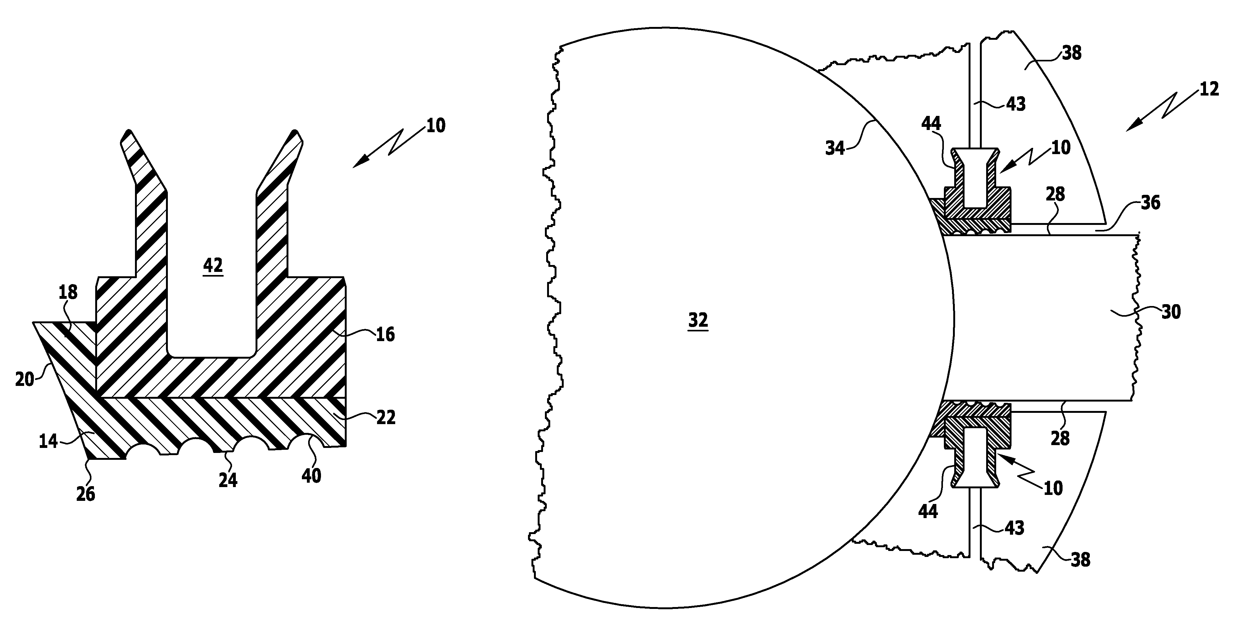
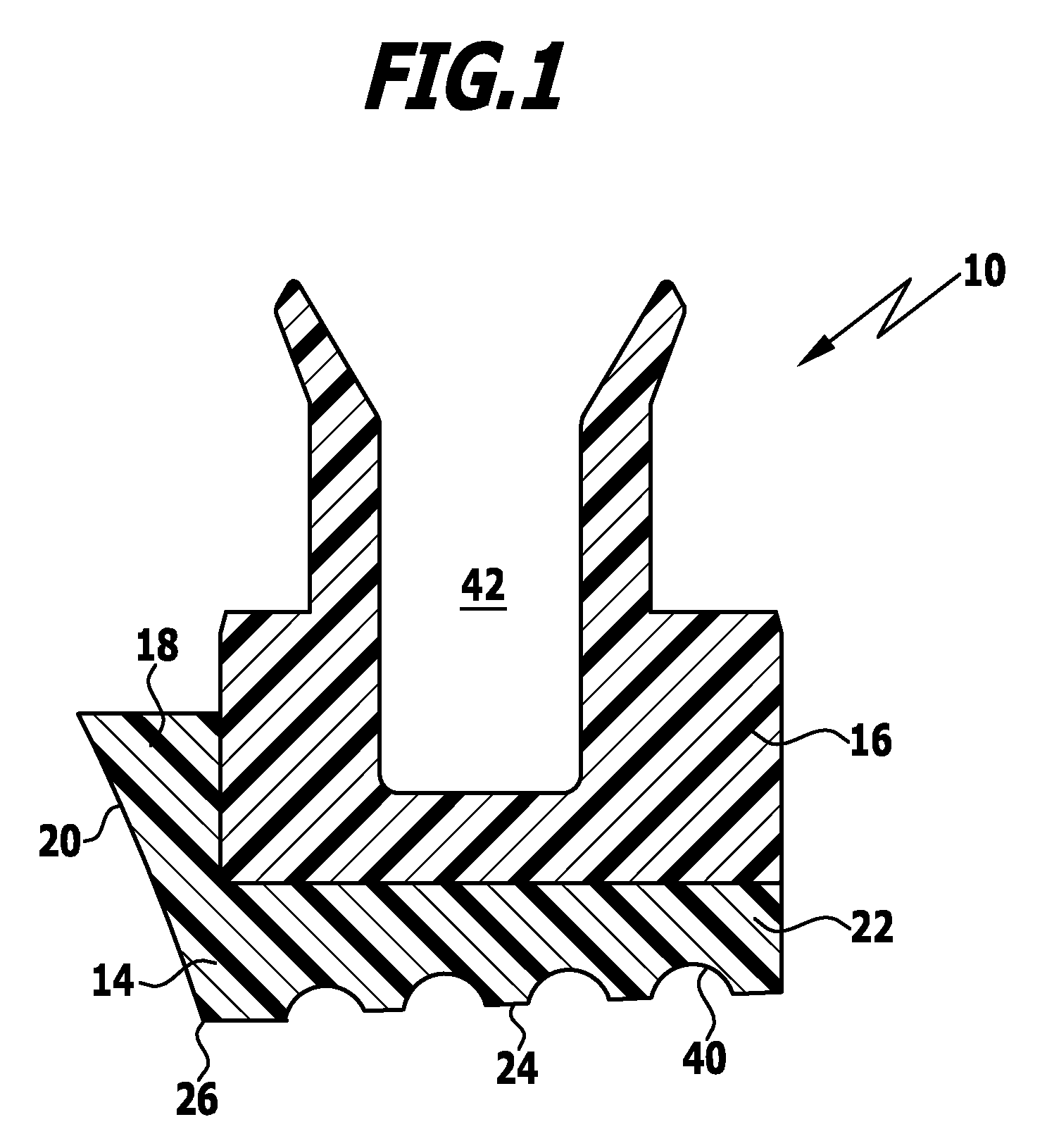
[0052]FIG. 1 shows a first exemplary embodiment of a sealing element according to the invention, which is given the overall reference 10. The sealing element 10 is rotationally symmetrical in the form of a ring or a partial arc of a circle, wherein a cross-section along a plane containing the rotational axis is shown in FIG. 1.

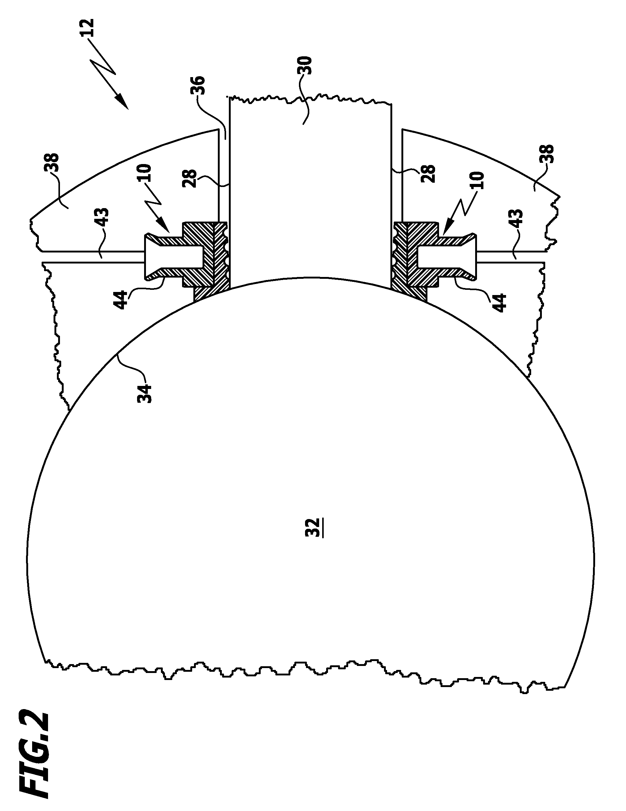
[0053]FIG. 2 shows a detail of a rotary piston machine 1 according to the invention, which comprises two sealing elements 10 according to the invention shown in FIG. 1. The structure and function of such a rotary piston machine are described in detail in DE 10 2007 001 021 A1.

[0054]The sealing element 10 comprises a first sealing part 14 and a second sealing part 16, which are both rotationally symmetrical relative to the rotational axis. The first sealing part 14 forms a dynamic region and the second sealing part 16 forms a static region of the two-part sealing element 10.

[0055]The first sealing part 14 is formed from a non-elastomeric fluoropolymer (e.g., PT...


PUM

PropertyMeasurementUnit
pressuresaaaaaaaaaa
melting pointaaaaaaaaaa
angleaaaaaaaaaa

Abstract

A sealing element for a rotary piston machine for sealing a lever is provided which is guided in an annular gap and is rotatable around a rotational axis, wherein the sealing element is rotationally symmetrical relative to the rotational axis, characterized in that the sealing element comprises a dynamic region and a static region, wherein the dynamic region has an axial sealing face being directed towards the annular gap, and a radial sealing face being directed towards the interior of an annular channel of the rotary piston machine, which annular channel surrounds the annular gap; and wherein the static region serves to fix the sealing element to the rotary piston machine, and wherein there is formed in the static region a channel, to which a fluid can be supplied.

Description

CROSS-REFERENCE TO RELATED APPLICATIONS[0001]The present application is a continuation of international application number PCT / EP2012 / 051076, filed on Jan. 25, 2012, which claims priority to German patent application number 10 2011 003 934.1, filed Feb. 10, 2011, the entire specification of both being incorporated herein by reference.FIELD OF THE INVENTION[0002]The present invention relates to a sealing element for a rotary piston machine for sealing a lever which is guided in an annular gap and is rotatable around a rotational axis, wherein the sealing element is rotationally symmetrical relative to the rotational axis.BACKGROUND OF THE INVENTION[0003]A rotary piston machine is described, for example, in DE 10 2007 001 021 A1. This comprises an annular channel, which is curved along an at least partial arc of a circle, and in which a piston can be caused to perform a movement along the arc by subjecting it to pressure with a fluid. This movement is transmitted by means of a lever c...

Claims


Application Information

Patent Timeline
Patent Type & Authority Patents(United States)
IPC IPC(8): F01C19/00F03C2/00F04C15/00F01C19/10F04C27/00F01B31/00F04C2/00F03C4/00F01C1/063F01C9/00
CPCF01B31/00F04C27/009F01C19/005F04C15/003F04C15/0038F01C19/10F05C2225/00F05C2225/04F01C1/063F01C9/002
Inventor RAUBACHER, HEINZKOCH, UWEVOIGT, MARKOALBER, MARKUS
Owner RAUBACHER HEINZ
Why Eureka
Try Eureka