
Shock absorber with hydraulic flow ducts

a technology of hydraulic flow ducts and shock absorbers, which is applied in the direction of vibration dampers, springs/dampers, springs, etc., can solve the problems of long overall length of dampers, difficult to fully control the pressure balance, and the ttx principle in this type of dampers

Active Publication Date: 2015-07-28
OHLINS
View PDF14 Cites 7 Cited by
  • Summary
  • Abstract
  • Description
  • Claims
  • Application Information

AI Technical Summary

Benefits of technology

[0012]The object of the present invention is to solve the problem of creating a uniform pressurization of two valves arranged in a shock absorber having a solid main piston, so as to ensure a positive pressure in the damping chambers without a turbulent flow, valve resonance or oil fluctuation occurring.
[0013]A further object of the invention is to solve this problem in a way that provides a simple, short damper of inexpensive design construction.SUMMARY OF THE INVENTION
[0020]The flow ducts are connected together by a through-passage, which also extends from the interior of the pressurization reservoir. Owing to the connection to the pressurization reservoir, the passage is pressurized with a pressure and can therefore be described as the chamber common to both of the damping chambers. When the two adjustable valves are also connected to one another via the through passage, one and the same pressure prevails in the valve chambers and on the first side of the valve core. Because the same pressure prevails at both of the valve cores, both of the valves always react equally rapidly to a change in pressure, whilst valve resonance is easier to prevent. In addition, the external dimensions can be minimized since the valves are located so close together.

Problems solved by technology

Arranging the pressurization reservoir in line with the body of the damper results in a long overall length of the damper, and requires a complicated manufacturing process in order to create the flow ducts between the pressurization reservoir and each damping chamber.
The limitation of the TTX principle in this type of damper lies in the area of the flow ducts and their capacity to transmit a sufficiently large flow of damping medium.
In addition, it has proved difficult to fully control the pressure balance in a damper having two adjustment points.
Further disadvantages are that a complete modification of the damping characteristic requires dismantling of the damper, whilst the pressure in the pressurizing reservoir has to be adjusted and balanced with the pressure in the damping chambers.
This means, however, that the ratio between the area of the main piston and the area of the flow ducts becomes critical for the flow of damping medium through the valves.
Creating a restriction of the damping medium flow in a vehicle damper having a positive pressure build-up and a solid main piston, without a turbulent flow occurring, has proved to be a problem.
There can also be a problem, when using a valve diameter smaller than the diameter of the main piston, in that the variation in the rate of flow via the damping ducts needs to be so great that disturbances and fluctuations can occur during movement of the oil.
Valve resonance can also occur, which can lead to jarring and an impaired damping function.
It can moreover be difficult to solve these problems without the damper assuming excessive dimensions, especially in a longitudinal direction, that is to say from fixing point to fixing point.

Method used


Image

  • Shock absorber with hydraulic flow ducts
  • Shock absorber with hydraulic flow ducts
  • Shock absorber with hydraulic flow ducts

Examples


Embodiment Construction

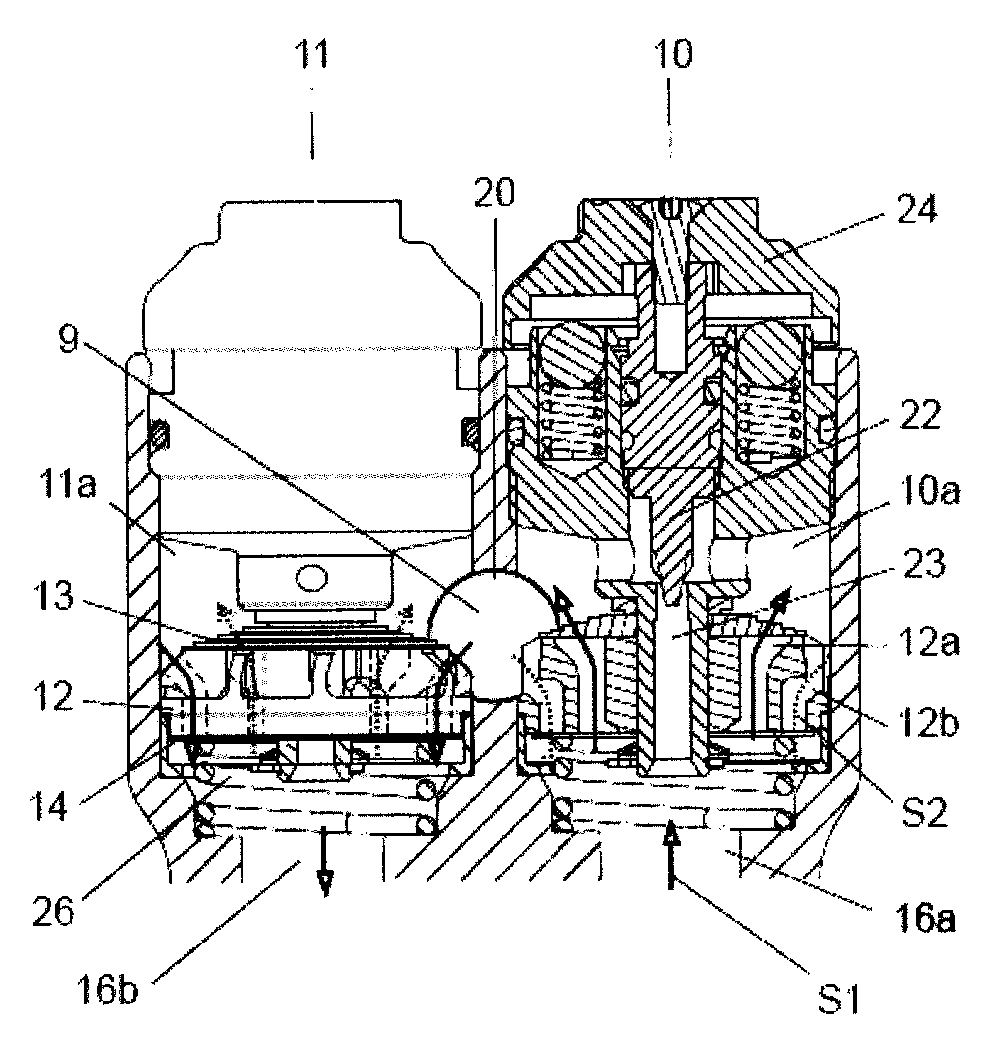
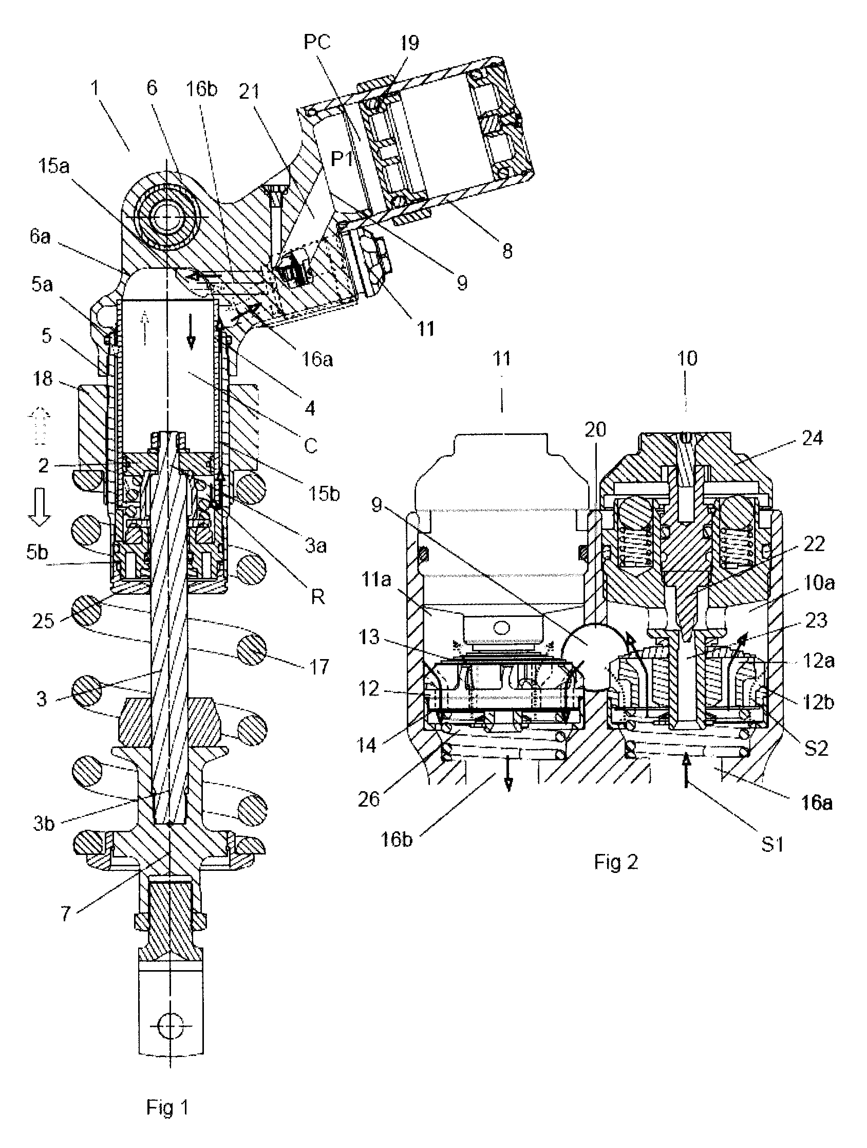
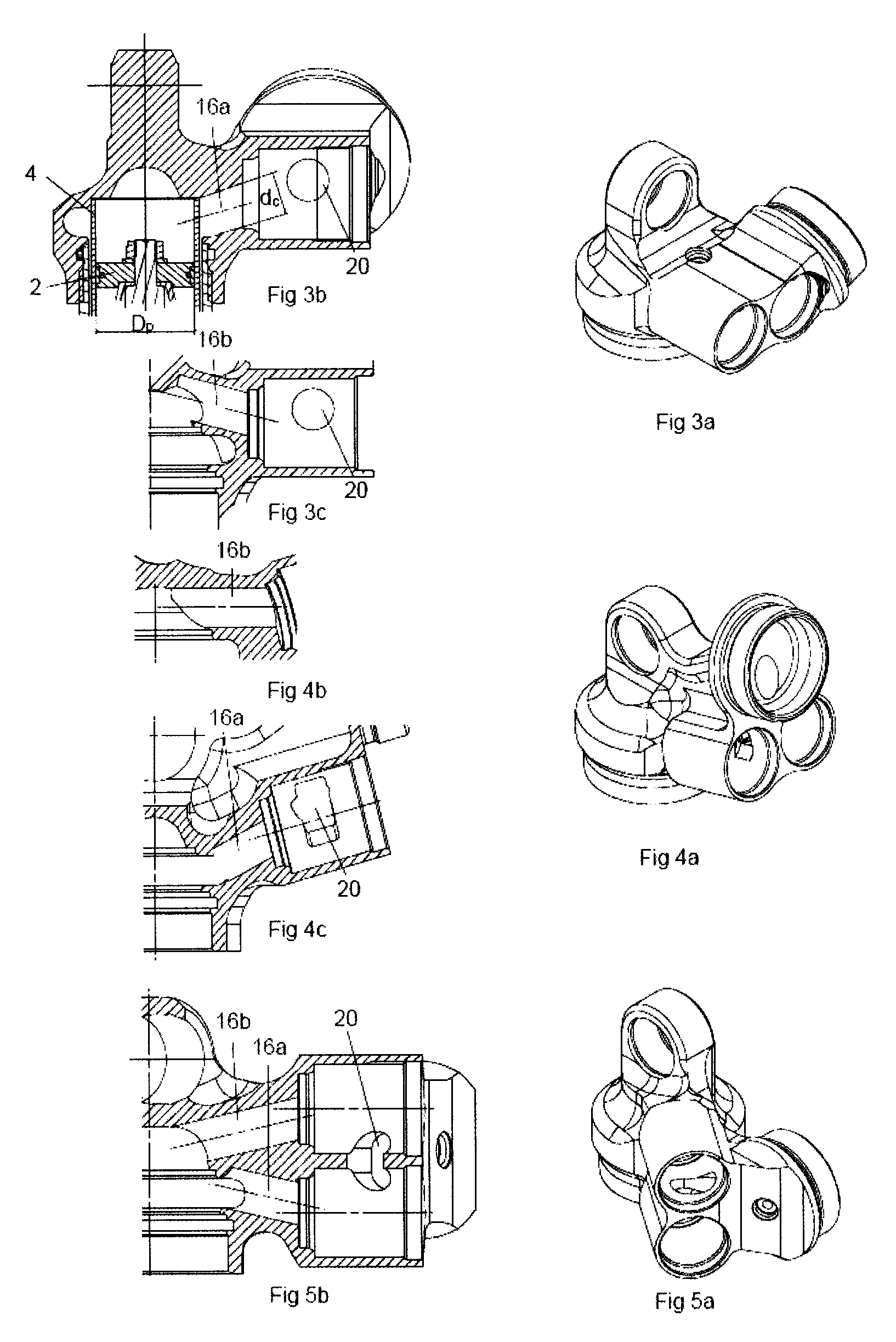
[0032]FIG. 1 shows a hydraulic shock absorber 1, which comprises a solid main piston 2 fixed to an upper part of a piston rod 3 and designed to slide in a damping cylinder 4. The term solid piston head implies that the piston does not allow any damping medium to pass through but is intended to compress or push in front of it all the damping medium on which the area of the piston acts during a movement. The damping cylinder 4 is defined by the main piston 2 in a first damping chamber R, containing the piston rod 3 and a second damping chamber C which does not contain the piston rod 3. Arranged around the damping cylinder 4 is an outer tube 5 having a diameter greater than the damping cylinder so that a gap is created between damping cylinder 4 and the outer tube 5. The outer tube 5 is defined at its first end 5a by a first fixing element 6 having an inner surface 6a, which adjoins the second damping cylinder C, and at its other end 5b by a sealing assembly 25. A second fixing element...


PUM


Abstract

The present invention provides a hydraulic shock absorber. A solid main piston is designed to slide in a damping cylinder parallel to the movement generated when the shock absorber is subjected to a compression or a rebound stroke, the main piston dividing the damping cylinder into a first damping chamber containing the piston rod and a second damping chamber which does not contain the piston rod. A pressurization reservoir is pressurized by a force acting on a moving piston. The pressurization reservoir is arranged outside the damping cylinder and oriented at an angle relative to the damping cylinder. Two separate, adjustable valves generate a damping force acting in opposition to the stroke movement by restricting a damping medium flow between the damping chambers. A fourth defined chamber is hydraulically connected via separate flow paths to both the first and the second damping chamber and the pressurization reservoir.

Description

TECHNICAL FIELD[0001]The present invention relates to a pressurized, damping medium-filled shock absorber having an externally located pressure reservoir, a so-called piggyback.BACKGROUND OF THE INVENTION[0002]In order to avoid cavitation whilst retaining a large adjustment range and a rapid response time even with large pressure differentials over the main piston, which divides a shock absorber into two damping medium-filled chambers, a compression chamber and a rebound chamber, use is currently made of a principle which is referred to by the applicant as so-called positive pressure build-up or TTX. A pressurized damper with positive pressure build-up always has a pressure greater than zero on both sides of the main piston arranged in the damping cylinder, regardless of what conditions prevail. Pressurization on both sides of the main piston is achieved in that a gas pressurized member, arranged in a pressurization reservoir, pressurizes a damping medium-filled chamber common to bo...

Claims


Application Information

Patent Timeline
Patent Type & Authority Patents(United States)
IPC IPC(8): F16F9/44F16F9/46F16F9/06
CPCF16F9/466F16F9/065
Inventor ISHII, ATSUSHIJARLMARK, ALEXANDRA
Owner OHLINS
Learn More