Shock absorber with hydraulic flow ducts

a technology of hydraulic flow ducts and shock absorbers, which is applied in the direction of vibration dampers, springs/dampers, springs, etc., can solve the problems of long overall length of dampers, difficult to fully control the pressure balance, and the ttx principle in this type of dampers

Active Publication Date: 2010-01-28
OHLINS
View PDF9 Cites 16 Cited by
  • Summary
  • Abstract
  • Description
  • Claims
  • Application Information

AI Technical Summary

Benefits of technology

[0012]The object of the present invention is to solve the problem of creating a uniform pressurization of two valves arranged in a shock absorber hav...

Problems solved by technology

Arranging the pressurization reservoir in line with the body of the damper results in a long overall length of the damper, and requires a complicated manufacturing process in order to create the flow ducts between the pressurization reservoir and each damping chamber.
The limitation of the TTX principle in this type of damper lies in the area of the flow ducts and their capacity to transmit a sufficiently large flow of damping medium.
In addition, it has proved difficult to fully control the pressure balance in a damper having two adjustment points.
Further disadvantages are that a complete modification of the damping characteristic requires dismantling of the damper, whilst the pressure in the pressurizing reservoir has to be adjusted and balanced with the pressure in the damping chambers.
This means, however, that the ratio between the are...

Method used


Image

  • Shock absorber with hydraulic flow ducts
  • Shock absorber with hydraulic flow ducts
  • Shock absorber with hydraulic flow ducts

Examples


Embodiment Construction

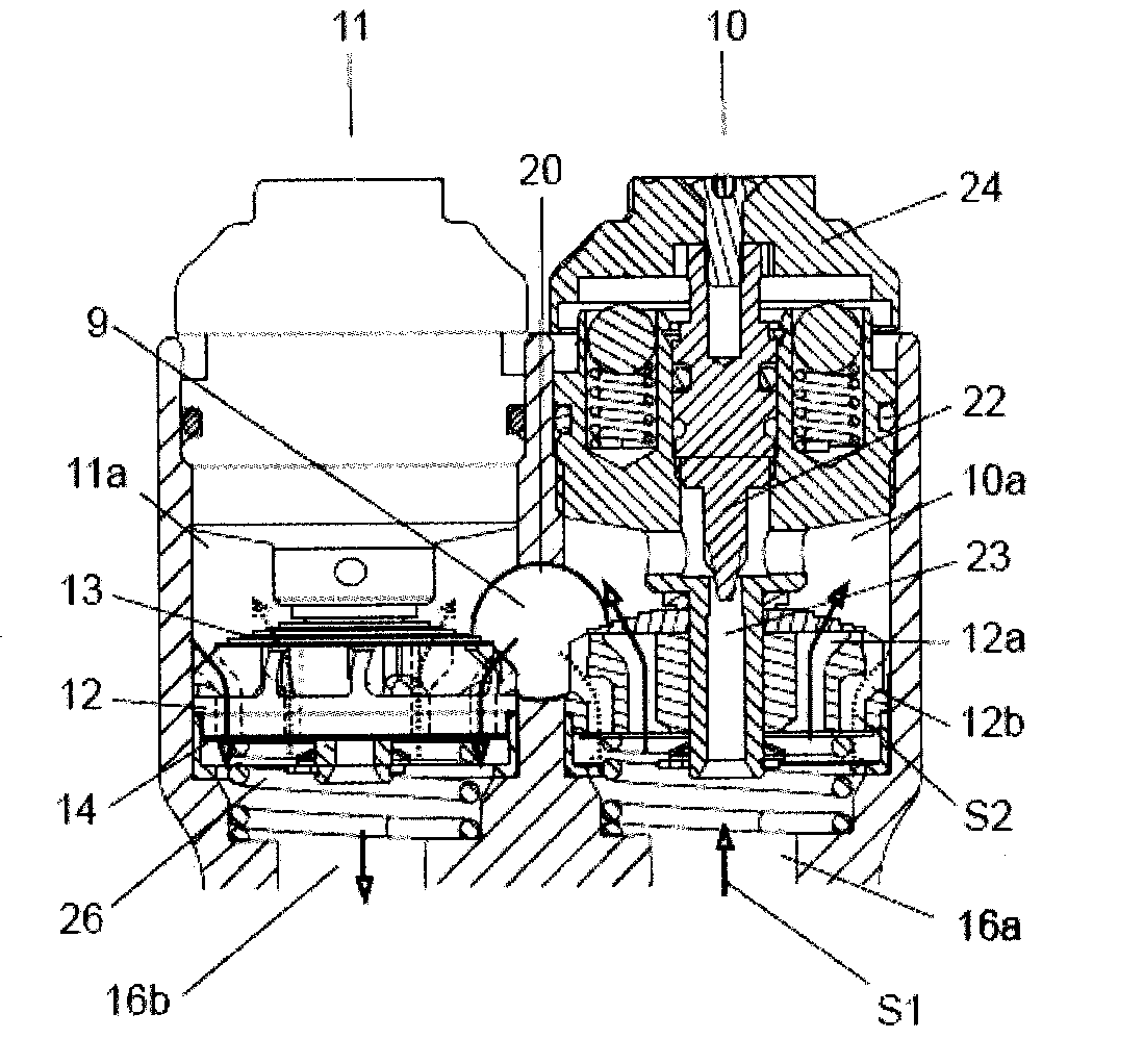
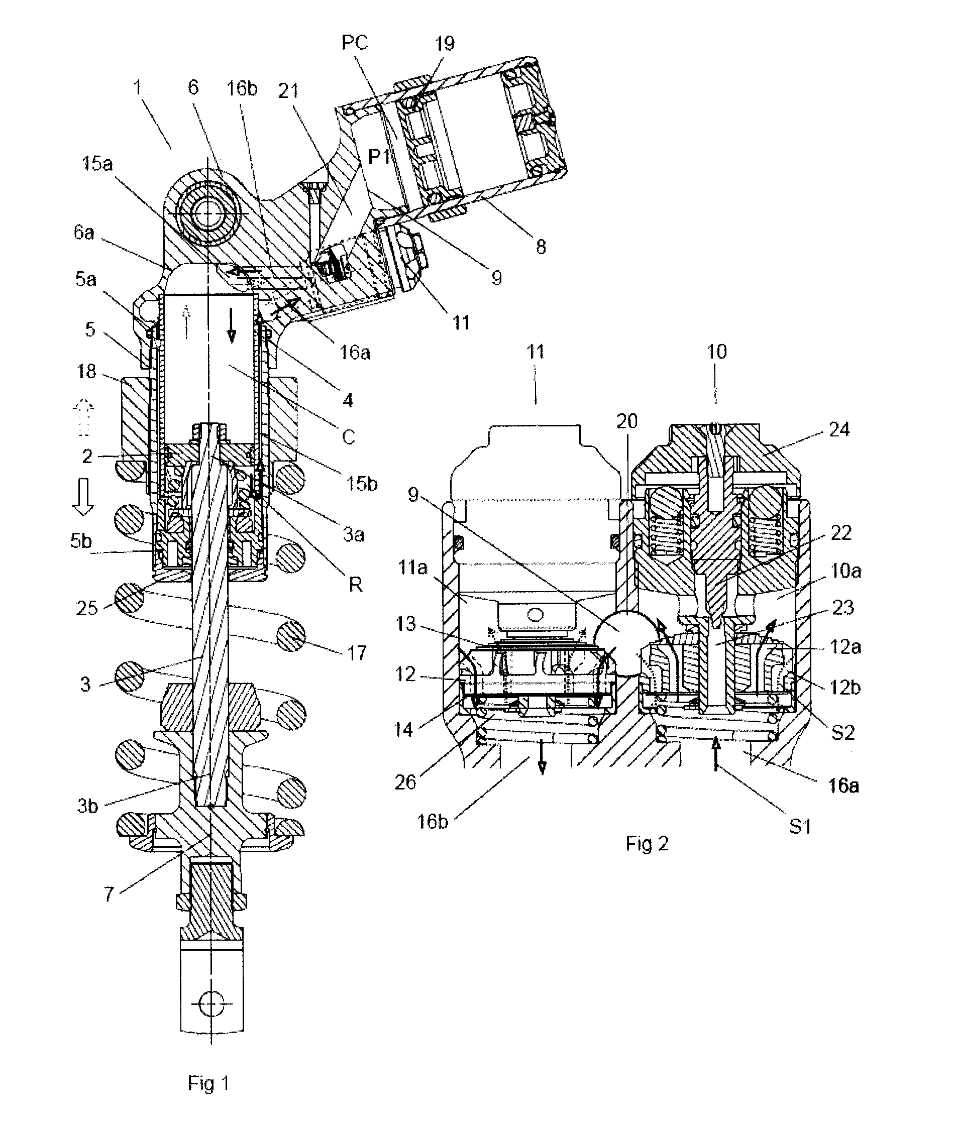
[0032]FIG. 1 shows a hydraulic shock absorber 1, which comprises a solid main piston 2 fixed to an upper part of a piston rod 3 and designed to slide in a damping cylinder 4. The term solid piston head implies that the piston does not allow any damping medium to pass through but is intended to compress or push in front of it all the damping medium on which the area of the piston acts during a movement. The damping cylinder 4 is defined by the main piston 2 in a first damping chamber R, containing the piston rod 3 and a second damping chamber C which does not contain the piston rod 3. Arranged around the damping cylinder 4 is an outer tube 5 having a diameter greater than the damping cylinder, so that a gap is created between the damping cylinder 2 and the outer tube 5. The outer tube 5 is defined at its first end 5a by a first fixing element 6 having an inner surface 6a, which adjoins the second damping chamber C, and at its other end 5b by a sealing assembly 25. A second fixing ele...


PUM


Abstract

The present invention provides a method and apparatus for a multilayer optical articles. A method comprises forming a first multilayer article with a first substrate, first adherent, and second substrate using a first holder and a second holder. The method further comprises forming a second multilayer article with the first multilayer article, a second adherent, and a third substrate using the first holder and second holder to grasp the second multilayer article. After removal of the first and second holders, the first and second adherent maintains the second multilayer article in a posture at which the second multilayer article was held by the first and second holders, wherein the first and second adherent comprise a photopolymer such that the article is capable of storing data in a reflective holographic data storage system.

Description

TECHNICAL FIELD[0001]The present invention relates to a pressurized, damping medium-filled shock absorber having an externally located pressure reservoir, a so-called piggyback.BACKGROUND OF THE INVENTION[0002]In order to avoid cavitation whilst retaining a large adjustment range and a rapid response time even with large pressure differentials over the main piston, which divides a shock absorber into two damping medium-filled chambers, a compression chamber and a rebound chamber, use is currently made of a principle which is referred to by the applicant as so-called positive pressure build-up or TTX. A pressurized damper with positive pressure build-up always has a pressure greater than zero on both sides of the main piston arranged in the damping cylinder, regardless of what conditions prevail. Pressurization on both sides of the main piston is achieved in that a gas pressurized member, arranged in a pressurization reservoir, pressurizes a damping medium-filled chamber common to bo...

Claims


Application Information

Patent Timeline
IPC IPC(8): F16F9/44
CPCF16F9/065F16F9/466
Inventor ISHII, ATSUSHIJARLMARK, ALEXANDRA
Owner OHLINS
Why Eureka
Try Eureka