System for fastening a rail in place and fastening for a rail

a technology of rails and fastening devices, applied in the direction of railway tracks, roads, constructions, etc., can solve the problem that the fastening process requires maintenance after only a comparatively short period of operation, and achieve the effect of minimising the emitted sound

Inactive Publication Date: 2015-09-22
VOSSLOH WERKE GMBH
View PDF22 Cites 1 Cited by
  • Summary
  • Abstract
  • Description
  • Claims
  • Application Information

AI Technical Summary

Benefits of technology

[0014]The guide plate has a supported surface by which it is supported on the base in the fitted position. Either the guide plate may rest directly on the base in this case or, if this is found to be necessary, a further layer, which serves to provide elastic support or protection against wear for example, may be present between the base and the guide plate.
[0036]Where the rail is supported on the solid base via an elastic layer, it may be advantageous, to minimise the emitted sounds, for the elastic layer to cover at least the foot of the rail and the web of the rail.

Problems solved by technology

Something which has proved to be a problem in the practical use of rail fastenings of the kind explained above is the fact that the fastening screws come loose, meaning that the fastening requires maintenance after operating for only a comparatively short period.

Method used


Image

  • System for fastening a rail in place and fastening for a rail
  • System for fastening a rail in place and fastening for a rail
  • System for fastening a rail in place and fastening for a rail

Examples


Embodiment Construction

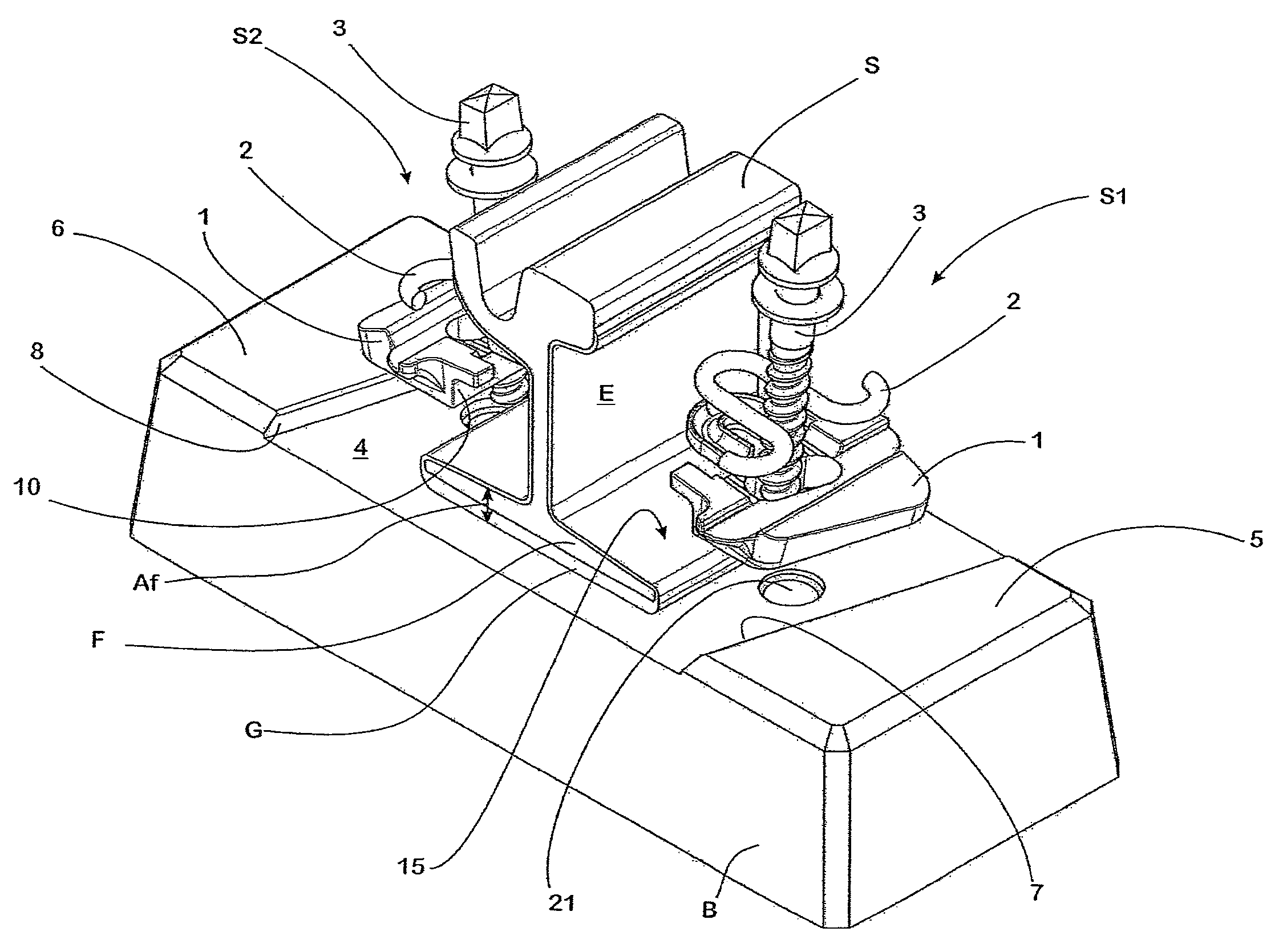
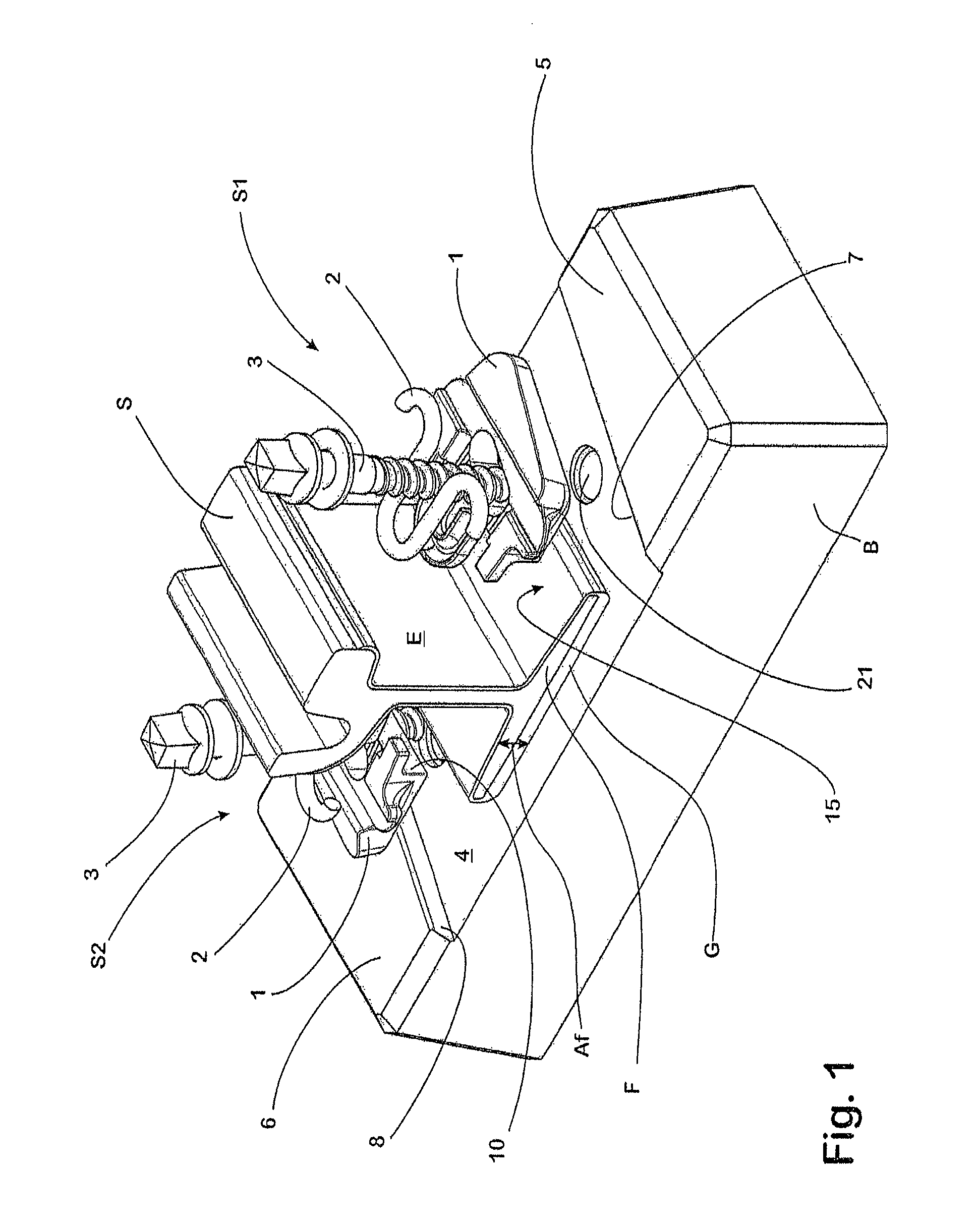
[0045]The rail S takes the form of a type of grooved rail and the fastening thereof to a solid base formed by a concrete sleeper B is accomplished by means two systems S1, S2 of similar design which each comprise a guide plate 1, a resilient member 2 and, as a clamping member, a clamping screw 3.

[0046]Formed in the concrete sleeper B is a plane supporting surface 4 which, at its longitudinal edges, meets the longitudinal sides of the sleeper B and which is bounded by respective shoulders 5, 6 at its narrow sides. The contacting surfaces 7, 8 of the shoulders 5, 6, which are associated with the supporting surface 4 and extend parallel to one another, each meet the longitudinal edges of the supporting surface 4 at an acute angle, thus giving the supporting surface 4 the form of a parallelogram in plan.

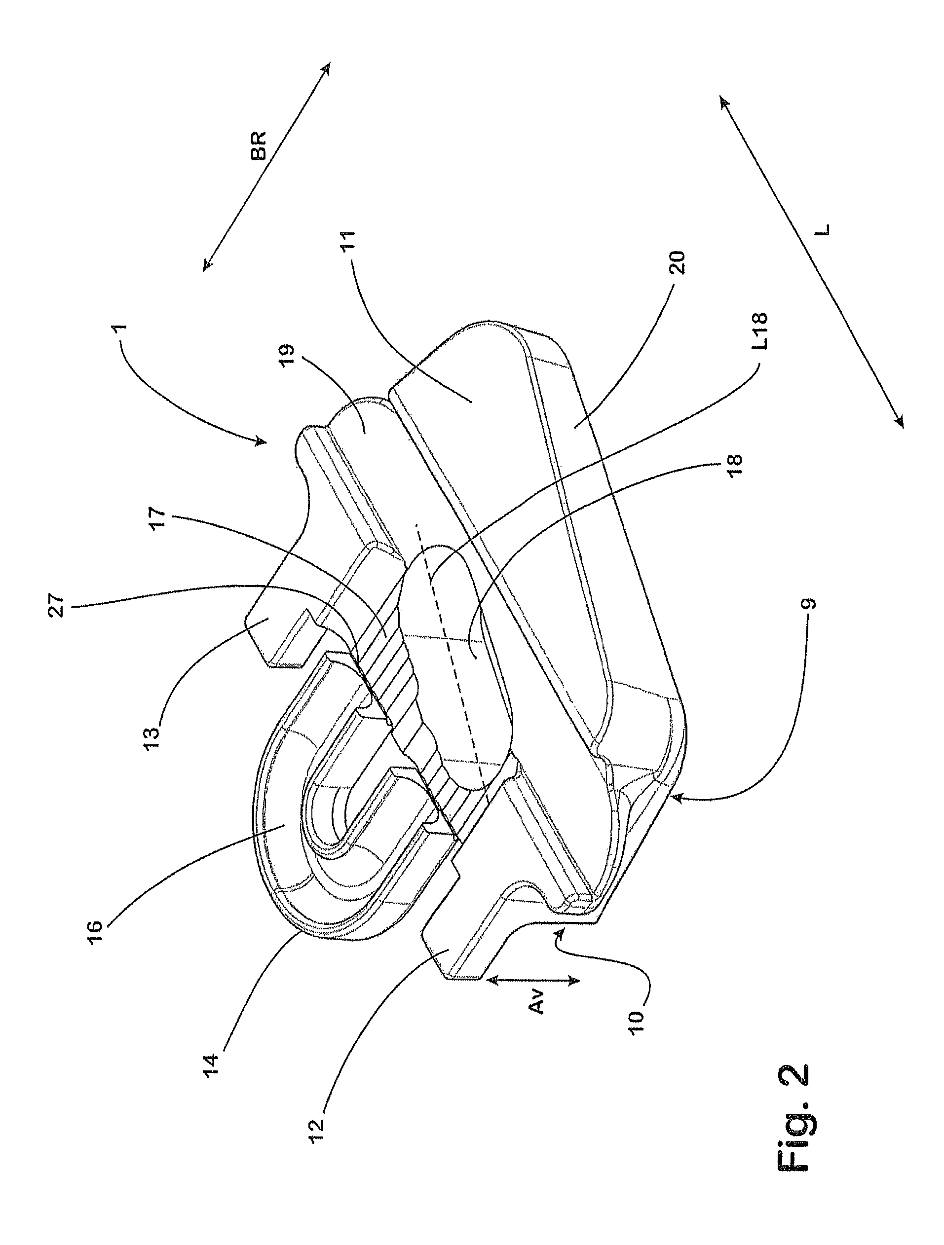
[0047]Each guide plate 1, which is made of a non-conductive plastics material which is for example fibre-reinforced, has on its underside a supported surface 9 by which it rests on the s...


PUM


Abstract

A system includes a guide plate, a fastening member and a resilient member, for fastening a rail on a solid base. The guide plate serves as a guide for the rail in the horizontal direction and as a stop for movements of the rail in the vertical direction. The guide plate has a contacting surface against which the longitudinal side of the foot of the rail rests. The resilient member which rests on the guide plate exerts substantially no hold-down force on the rail and merely supports the guide plate elastically against the clamping member. The resilient member is of a W-shaped or S-shaped configuration and, in the fitted state, a portion thereof projects sufficiently far over the foot of the rail for it to be retained resiliently by the resilient member if it is moved upwards in the vertical direction.

Description

BACKGROUND OF THE INVENTION[0001]1. Field of the Invention[0002]The invention relates to a system for fastening a rail in place on a base and to a fastening for a rail which uses such a system.[0003]2. Description of Related Art[0004]When rails are to be fastened in place on which travel takes place with quite low loads and at quite low speeds, as is the case with tramways for example, the primary concerns are on the one hand wear which is as low as possible and on the other hand a comfortable ride and the minimising of emitted sounds. At the same time, such fastenings are also intended to be able to be fitted easily and to be able to be manufactured inexpensively.[0005]In the rail fastenings which are used in practice, these requirements are met by mounting the rails on a solid base formed for example by a concrete sleeper or an isolated support made of concrete, with an elastic layer having a defined ability to yield being arranged between the foot of the rail and the solid base. ...

Claims


Application Information

Patent Timeline
Patent Type & Authority Patents(United States)
IPC IPC(8): E01B9/62E01B13/02E01B9/30E01B9/66
CPCE01B9/303E01B9/66
Inventor BOSTERLING, WINFRIEDRADEMACHER, LUTZBEDNARCZYK, ADRIAN
Owner VOSSLOH WERKE GMBH
Why Eureka
Try Eureka