Hinge with damping device

Active Publication Date: 2015-10-20
KING SLIDE WORKS CO LTD +1
View PDF21 Cites 40 Cited by
  • Summary
  • Abstract
  • Description
  • Claims
  • Application Information

AI Technical Summary

Benefits of technology

[0013]One of the features of the embodiments of the present invention is that the adjusting member has at least two contact portions which enable the piston rod of the dampe

Problems solved by technology

Lacking a damping function adjusting mechanism, the damping devi

Method used


Image

  • Hinge with damping device
  • Hinge with damping device
  • Hinge with damping device

Examples


Embodiment Construction

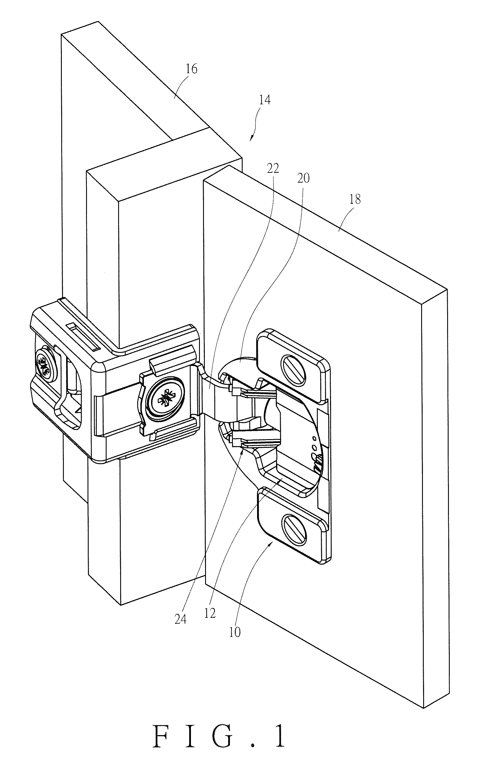
[0028]FIG. 1 shows how a hinge 10 and a damping device 12 in an embodiment of the present invention are applied to a cabinet 14 (e.g., a cupboard or a similar piece of furniture). The cabinet 14 has a fixed portion 16 and a door 18. The door 18 can be opened and closed with respect to the fixed portion 16.

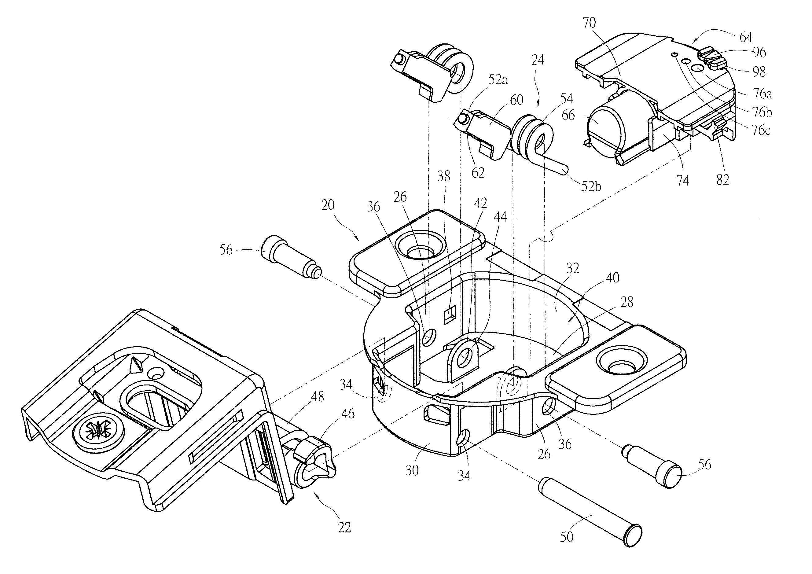
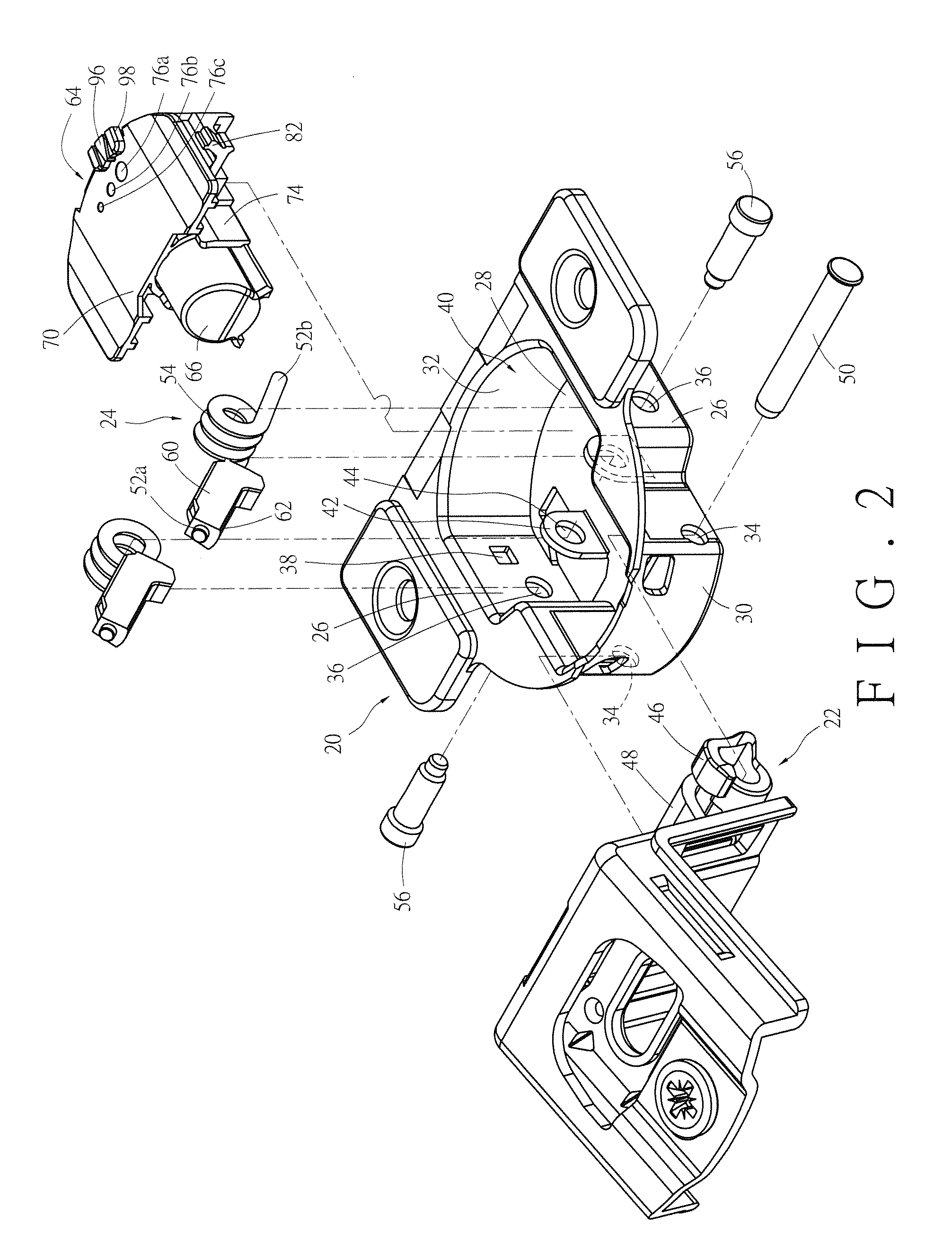
[0029]The hinge 10 includes a hinge cup 20, a hinge arm 22, and at least one spring 24. The hinge cup 20 is pivotally connected to the hinge arm 22 and is mounted to the door 18 of the cabinet 14. The hinge arm 22, on the other hand, is mounted to the fixed portion 16 of the cabinet 14. When the door 18 of the cabinet 14 is closed (or opened) with respect to the fixed portion 16, the hinge cup 20 is closed (or opened) with respect to the hinge arm 22. The at least one spring 24 and the damping device 12 are mounted in the hinge cup 20. In the course in which the hinge cup 20 is opened with respect to the hinge arm 22, the hinge cup 20 responds to the force generated by the at least...


PUM


Abstract

A hinge includes a hinge arm, a hinge cup, a spring, a retainer, a damper, and an adjusting member. When the hinge cup, which is pivotally connected to the hinge arm, is being closed relative thereto, the spring provides a resilient closing force to complete the closing action. The retainer is mounted in the hinge cup and has a channel. The damper is mounted in the channel and corresponds to the hinge arm to provide a damping force adjustable via the adjusting member, which is movably mounted to the retainer, includes a surface and at least two contact portions differently spaced from the surface, and can be adjusted relative to the retainer so that one of the contact portions corresponds to the damper.

Description

FIELD OF THE INVENTION[0001]The present invention relates to a hinge and, more particularly, to a hinge having a damping device capable of different damping actions.BACKGROUND OF THE INVENTION[0002]U.S. Pat. No. 8,561,262 B1 discloses a damping device for a hinge assembly. According to its specification, the damping hinge assembly includes a housing (10), an arm (12), at least one spring (14), a maintaining member (16), a damper (18), and an adjustment member (20). The arm (12) is pivotally connected to the housing (10). The housing (10) includes a chamber (36). The spring (14) is mounted in the chamber (36) of the housing (10) and serves to provide a resilient closing force when the housing (10) is pivoted with respect to the arm (12) and is thereby being closed with respect thereto.[0003]The maintaining member (16) is fixedly mounted in the chamber (36) of the housing (10) and has a path (72) for receiving the damper (18). The damper (18) is mounted in the path (72) of the maintai...

Claims


Application Information

Patent Timeline
IPC IPC(8): E05F1/08E05F5/00E05D7/00
CPCE05F5/006E05D7/00E05F5/02E05Y2201/21E05Y2201/214E05Y2201/256E05Y2201/264E05Y2900/20E05Y2201/22E05F3/20
Inventor LIANG, HSIU-CHIANGCHEN, KEN-CHINGWANG, CHUN-CHIANG
Owner KING SLIDE WORKS CO LTD
Why Eureka
Try Eureka