
Short tail recovery techniques in wire bonding operations

a recovery technique and wire bonding technology, applied in the direction of manufacturing tools, non-electric welding apparatus, testing/measurement of semiconductor/solid-state devices, etc., can solve the problem of inconsistent free air ball size and shap

Active Publication Date: 2015-10-20
KULICKE & SOFFA IND INC
View PDF18 Cites 4 Cited by
  • Summary
  • Abstract
  • Description
  • Claims
  • Application Information

AI Technical Summary

Problems solved by technology

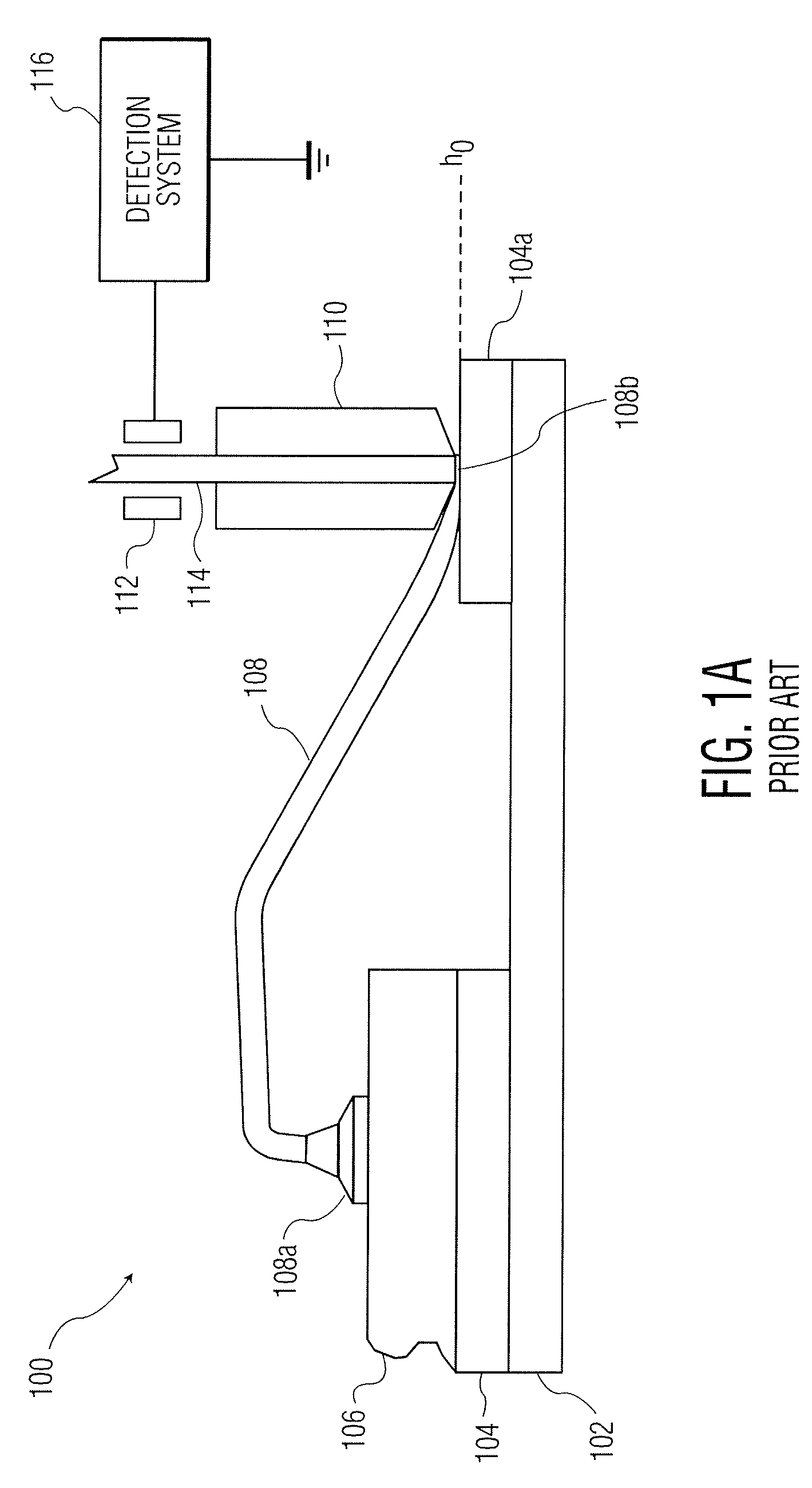
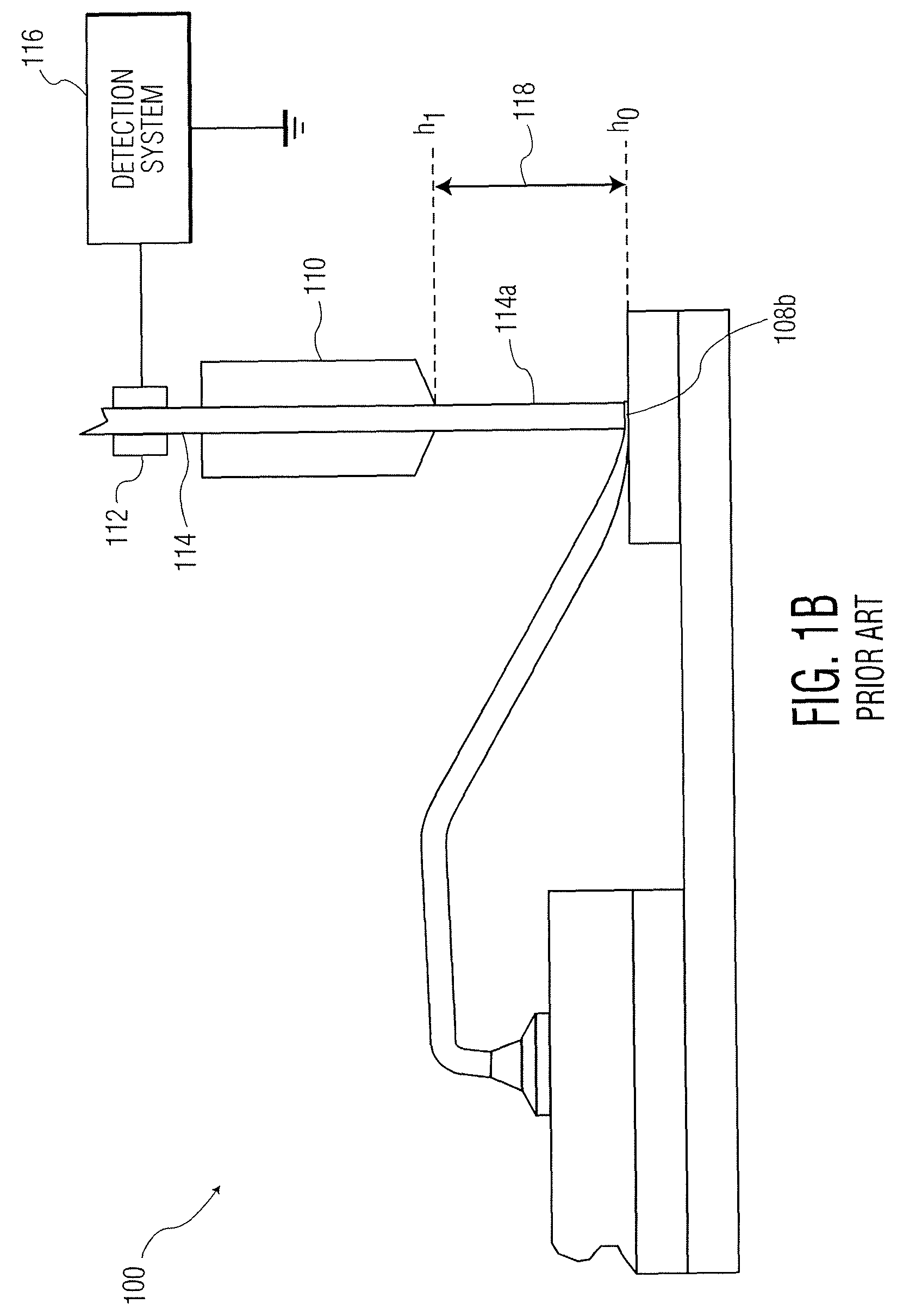
Short tail conditions may result in a number of problems during wire bonding such as, for example, inconsistent free air ball size and shape.

Method used


Image

  • Short tail recovery techniques in wire bonding operations
  • Short tail recovery techniques in wire bonding operations
  • Short tail recovery techniques in wire bonding operations

Examples


Embodiment Construction

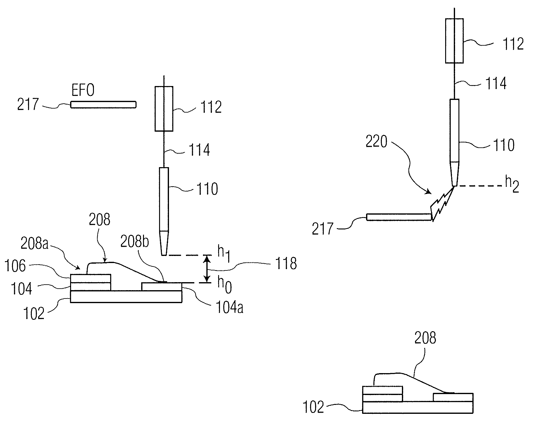
[0015]In accordance with various exemplary embodiments of the present invention, a method of recovering from a “short tail” condition is provided. By providing for the recovery of the short tail, the overall mean time between assists (i.e., MTBA) of the machine is extended by recovering after a short tail has occurred. As detailed herein, after a short tail condition is detected, a process may be performed (e.g., using a software algorithm on the wire bonding machine) to control a z-axis motion system and a wire clamp to create a sequence where the wire is recovered after a short tail is detected.

[0016]As will be appreciated by those skilled in the art, certain motions of a wire bonding tool follow an acceleration / deceleration profile (e.g., an “S” curve). For example, during certain descending motions toward a workpiece, the wire bonding tool accelerates toward the workpiece. During the descent, the wire bonding tool decelerates while still being moved toward the workpiece. By open...


PUM


Abstract

A method of operating a wire bonding machine is provided. The method includes: detecting a short tail condition after formation of a wire bond formed using a wire bonding tool; providing a bond head assembly of a wire bonding machine at an xy location of the wire bonding machine, the bond head assembly carrying the wire bonding tool; lowering the bond head assembly toward a contact surface at the xy location with a wire clamp of the wire bonding machine closed; opening the wire clamp; decelerating the bond head assembly as it is lowered toward the contact surface such that a portion of a wire extends below a tip of the wire bonding tool; closing the wire clamp; and performing a test to determine if an end of the portion of the wire extending below the tip of the bonding tool is in contact with the contact surface.

Description

CROSS REFERENCE TO RELATED APPLICATION[0001]This application claims the benefit of U.S. Provisional Patent Application No. 61 / 927,688 filed Jan. 15, 2014, the content of which is incorporated herein by reference.FIELD OF THE INVENTION[0002]The present invention relates to wire bonding operations (e.g., the formation of wire loops, the formation of conductive bumps, etc.), and in particular, to techniques for recovering from short tail conditions in wire bonding operations.BACKGROUND OF THE INVENTION[0003]In the processing and packaging of semiconductor devices, wire bonding continues to be the primary method of providing electrical interconnection between two locations within a package (e.g., between a die pad of a semiconductor die and a lead of a leadframe). More specifically, using a wire bonder (also known as a wire bonding machine) wire loops are formed between respective locations to be electrically interconnected. The primary methods of forming wire loops are ball bonding and...

Claims


Application Information

Patent Timeline
Patent Type & Authority Patents(United States)
IPC IPC(8): B23K31/02H01L21/66H01L23/00B23K20/00
CPCB23K20/004B23K20/005B23K20/007H01L22/14H01L24/85H01L22/12H01L2224/4845H01L2224/78821H01L2224/851H01L2224/859H01L2224/85365H01L2924/00014H01L2224/85203H01L2224/85205H01L2224/85207H01L24/78H01L2224/32225H01L2224/48227H01L2224/48465H01L2224/73265H01L2224/78301H01L2224/85045H01L2224/85181H01L24/48H01L2224/789H01L2224/85009H01L2224/78631H01L2224/78621H01L2224/45099H01L2924/00
Inventor GILLOTTI, GARY S.
Owner KULICKE & SOFFA IND INC
Learn More