Recessed groove for better suture retention

a recessed groove and suture technology, applied in the direction of surgical staples, etc., can solve the problem that the retention system diminishes the likelihood of premature suture release during assembly

Active Publication Date: 2015-11-24
TYCO HEALTHCARE GRP LP
View PDF451 Cites 1311 Cited by
  • Summary
  • Abstract
  • Description
  • Claims
  • Application Information

AI Technical Summary

Problems solved by technology

This retention system diminishes the likelihood of premature suture release during assembly, packing or firing.

Method used


Image

  • Recessed groove for better suture retention
  • Recessed groove for better suture retention
  • Recessed groove for better suture retention

Examples


Embodiment Construction

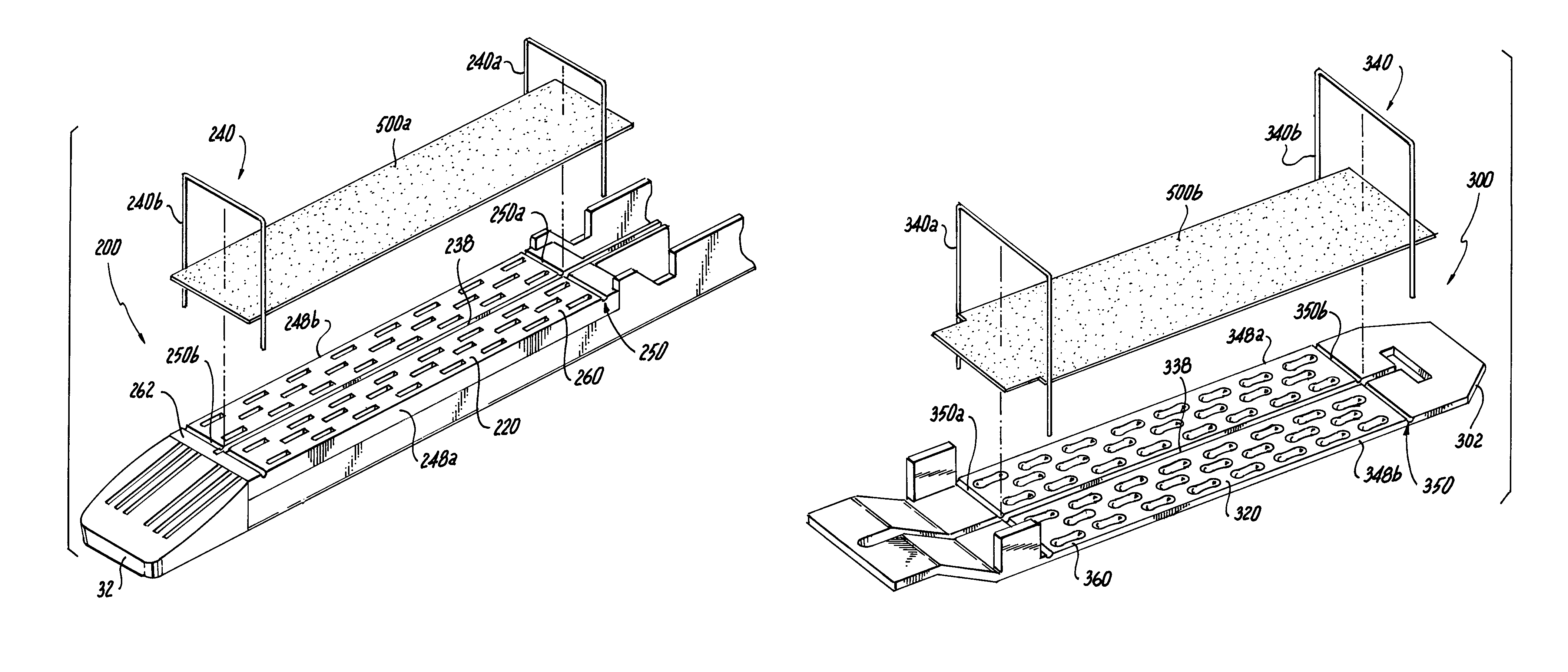
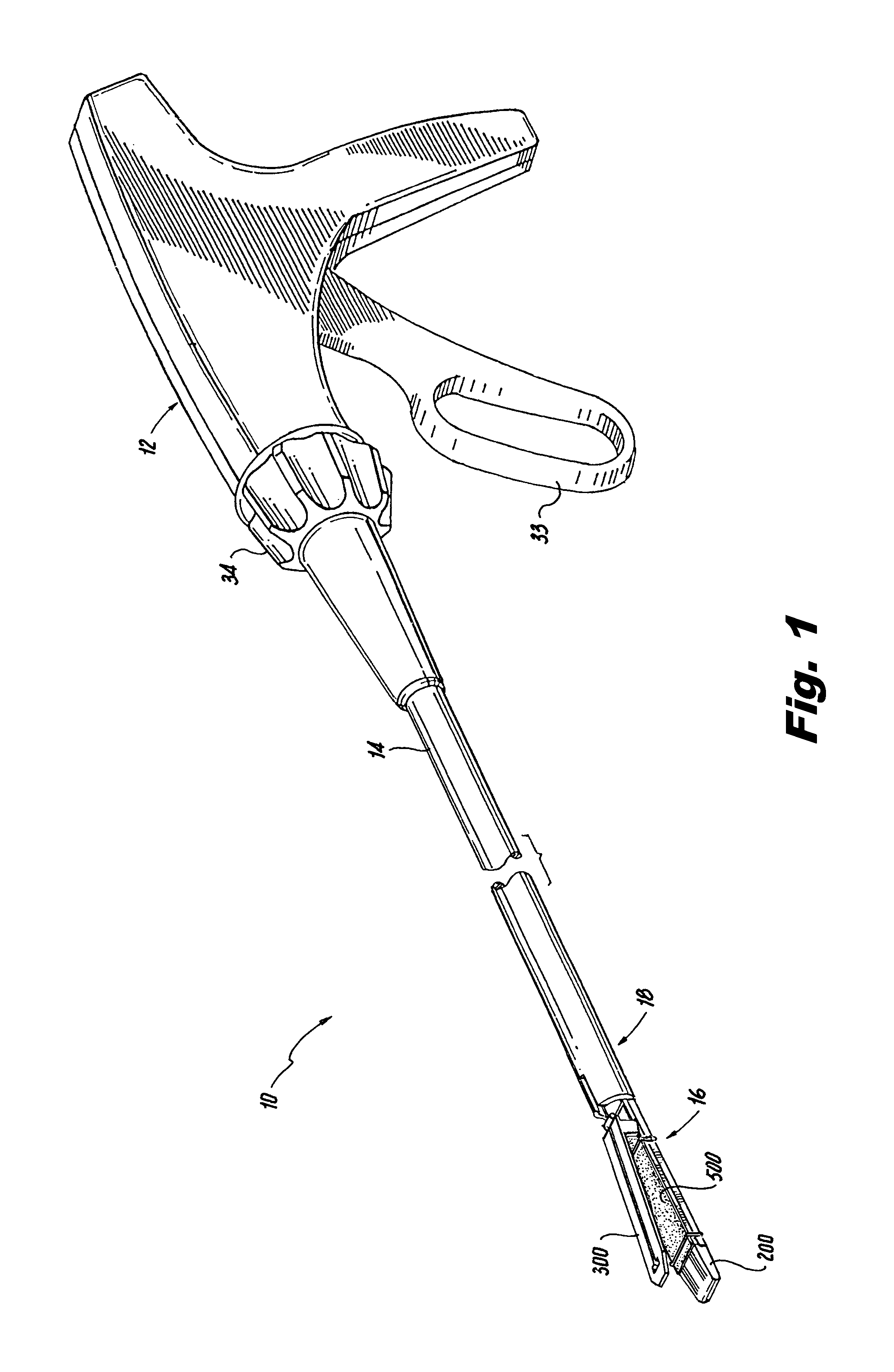
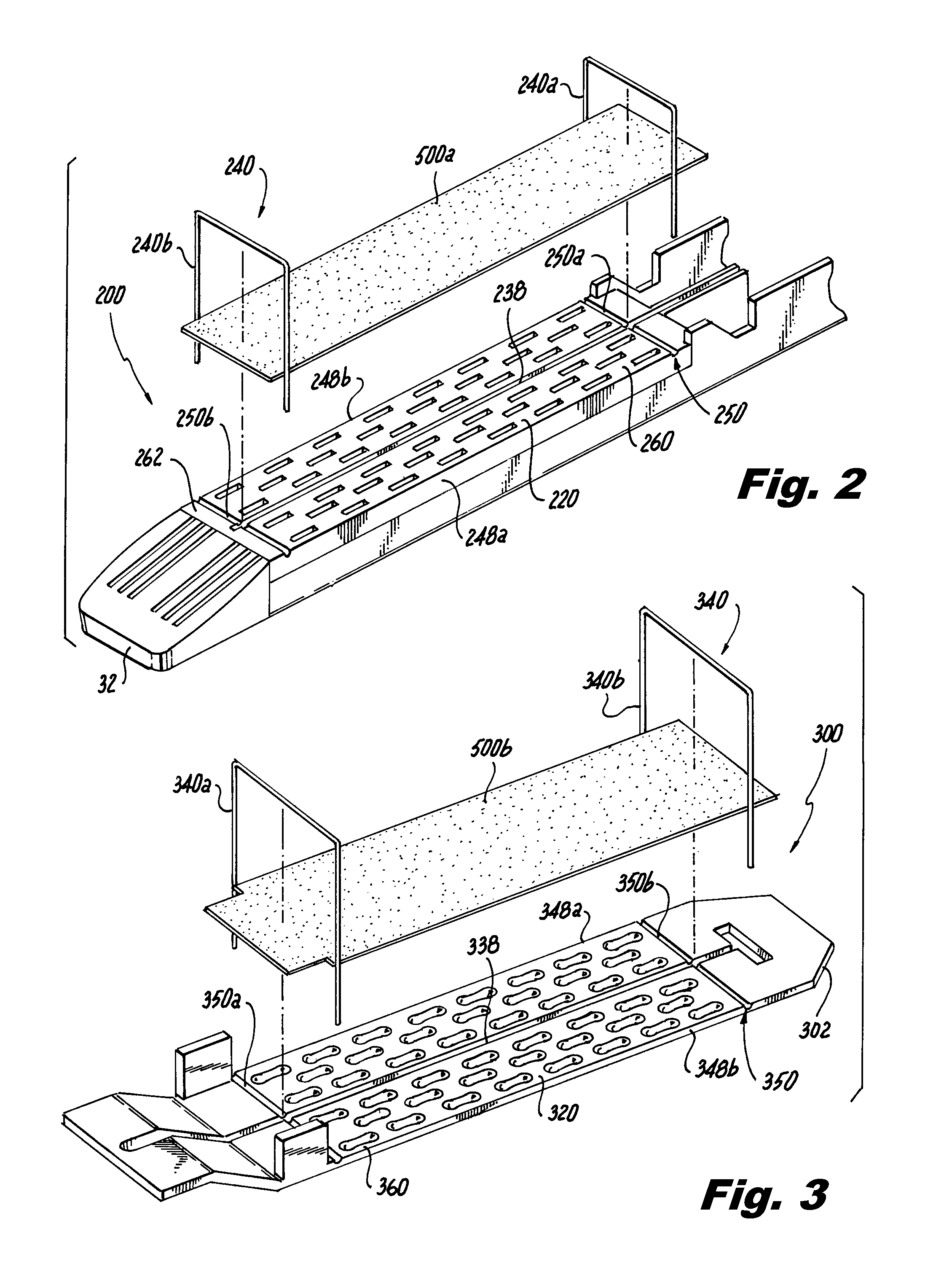
[0030]Various exemplary embodiments of the present disclosure are discussed herein below in terms of surgical buttresses for use with surgical stapling apparatus. The surgical buttresses described herein may be used in sealing a wound by approximating the edges of wound tissue between a staple cartridge and an anvil plate of a surgical stapling apparatus which contains at least one surgical buttress. The at least one surgical buttress is joined to the surgical stapling apparatus by at least one suture disposed within a recessed groove of a tissue contacting surface of each of a staple cartridge and anvil plate. Firing of the surgical stapling apparatus forces legs of at least one staple to pass through an opening on the staple cartridge, the tissue, and the openings on the anvil plate to secure the surgical buttress to the tissue, to secure the adjoining tissue to one another, and to seal the tissue. The firing force of the staple impacts the suture to release the suture from the re...


PUM


Abstract

An end effector for use with a surgical stapler. The end effector comprising a staple cartridge having a tissue contacting surface having at least one recessed groove defined therein and an anvil plate having a tissue contacting surface having at least one recessed groove defined therein. A surgical buttress releasably disposed on the tissue contacting surfaces of each of the staple cartridge and the anvil plate. At least one suture is disposed within the at least one recessed groove of each of the staple cartridge and anvil plate and configured to retain the respective surgical buttress atop the respective tissue contacting surface.

Description

BACKGROUND[0001]1. Technical Field[0002]The present disclosure relates to surgical stapling apparatus including surgical buttresses which can be releasably attached to the surgical stapling apparatus, and in particular, to surgical stapling apparatus having sutures disposed within recessed grooves therein. Sutures join the surgical buttress to the surgical stapling apparatus such that the surgical buttress is released upon firing of the surgical stapling apparatus.[0003]2. Background of Related Art[0004]Surgical stapling instruments that are used to sequentially or simultaneously apply one or more rows of fasteners to join segments of body tissues are well known in the art. The fasteners are typically in the form of surgical staples but two part polymeric fasteners can also be utilized. Such devices generally include a pair of jaws to clamp therebetween the body tissues to be joined. Typically, one of the jaw members includes a staple cartridge which accommodates a plurality of stap...

Claims


Application Information

Patent Timeline
Patent Type & Authority Patents(United States)
IPC IPC(8): A61B17/072A61B17/115
CPCA61B17/07292A61B17/1155A61B2017/07257A61B2017/07271
Inventor BETTUCHI, MICHAEL J.
Owner TYCO HEALTHCARE GRP LP
Why Eureka
Try Eureka