Orthopedic field splint

a technology for orthopaedic splints and splints, applied in the field of orthopaedic splints, can solve the problems of large and relatively heavy, long time-consuming and laborious, and inability to work with vacuum splints

Active Publication Date: 2016-01-05
AMODT ZACHARY T
View PDF6 Cites 13 Cited by
  • Summary
  • Abstract
  • Description
  • Claims
  • Application Information

AI Technical Summary

Problems solved by technology

The vacuum splint does not work if the splint is punctured.
The vacuum splint may also require extended time to remove after it has been applied.
Although the traction splint may be folded in half, it is large and relatively heavy, and may be difficult for an operator can carry.
Without an X-ray of the injured leg, the traction splint may be improperly applied.
Although relatively light and portable, inflating the air splint is time consuming and may require more time than the operator has available.
The air splint will not inflate if punctured, such as if shot, rendering the air splint non-functional.
The air splint does not allow further treatment of injuries (such as bleeding), and must be completely removed if further aid is necessary.
The air splint may not function properly work if bulky bandages are applied to the limb, as it may not fit over the bandages.
The SAM® splint is easy to bend, but does not offer much rigidity.
Due to its size, it is not useful for larger fractures such those found in the leg (other than the ankle) and is most useful for wrist and ankle injuries.
This device does not offer any immobilization of the limb.
It is also very difficult to place on the patient.
When the ladder splint is bent before application, it can be difficult for the operator / medic to form the splint in to the correct shape.
The ladder splint also has to be cut and formed which requires time that the operator / medic may not have available.
Also, because the ladder splint is easy to bend, it is a less than ideal splint.
It is bulky, heavy, difficult to assemble, and requires a relatively long period of time to assemble and to fit on the patient.
This splint is large, and its use is limited to vehicle accident victims.
The field-expedient splint folds and rolls to become more compact, however it takes a long time to make, making it imperfect in emergency situations.

Method used


Image

  • Orthopedic field splint
  • Orthopedic field splint
  • Orthopedic field splint

Examples


first embodiment

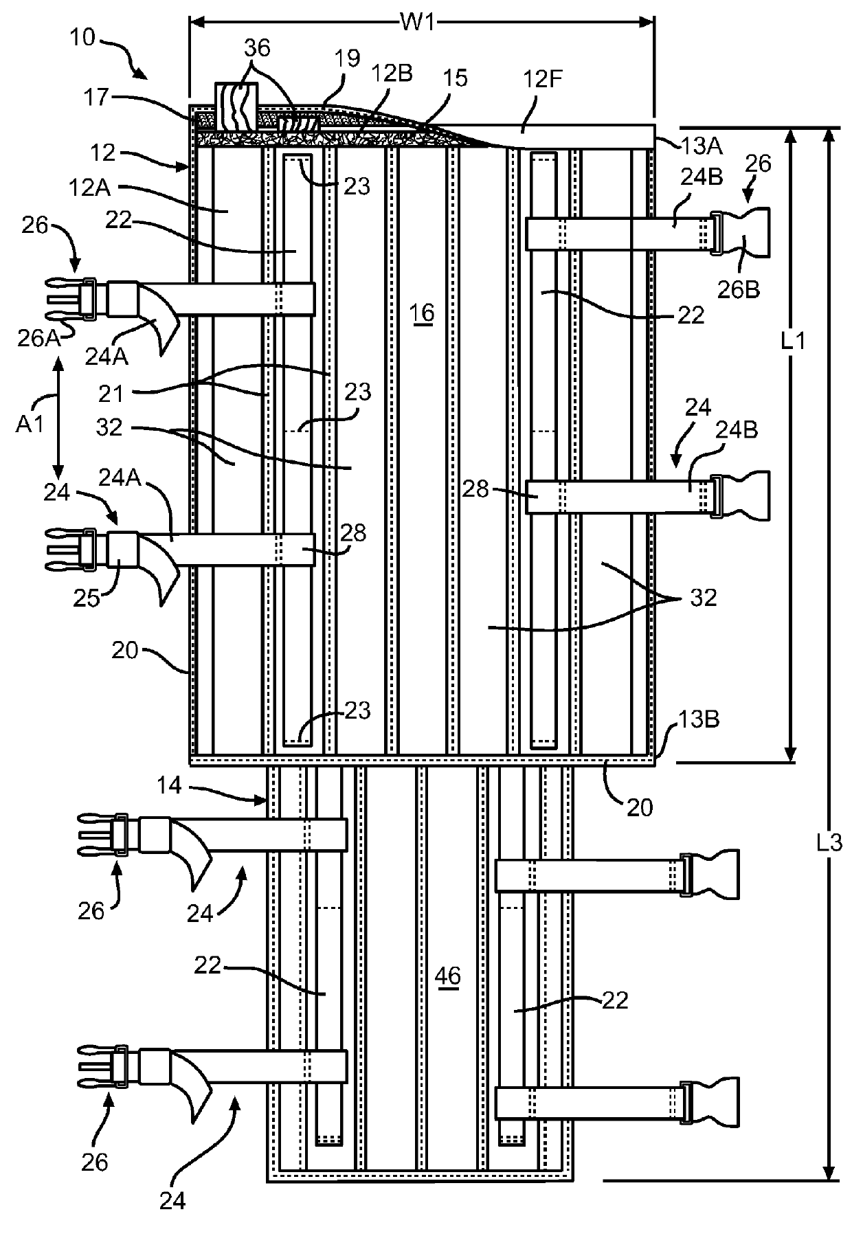
[0024]Referring now to the drawings, there is illustrated in FIG. 1 an orthopedic splint, indicated generally at 10, in accordance with this invention. As shown in FIG. 1, the splint 10 is in an unfolded or open position.

[0025]The illustrated splint 10 includes a first member 12 and a second member 14. The first and second members 12 and 14 are substantially rectangular and are formed from substantially flexible material such as nylon. Alternatively, the first and second members 12 and 14 may have other shapes and may be formed from other substantially flexible material or webbing, and may comprise multiple layers of fabric and / or webbing. The substantially flexible material or webbing may also be formed from other material, such as KEVLAR® fabric, GORTEX® fabric, ballistic nylon fabric, polyester and cotton blended fabric, polyester fabric, ripstop nylon fabric, and other like materials.

[0026]In the illustrated embodiment, the splint 10 is configured for use on a leg of an average ...

second embodiment

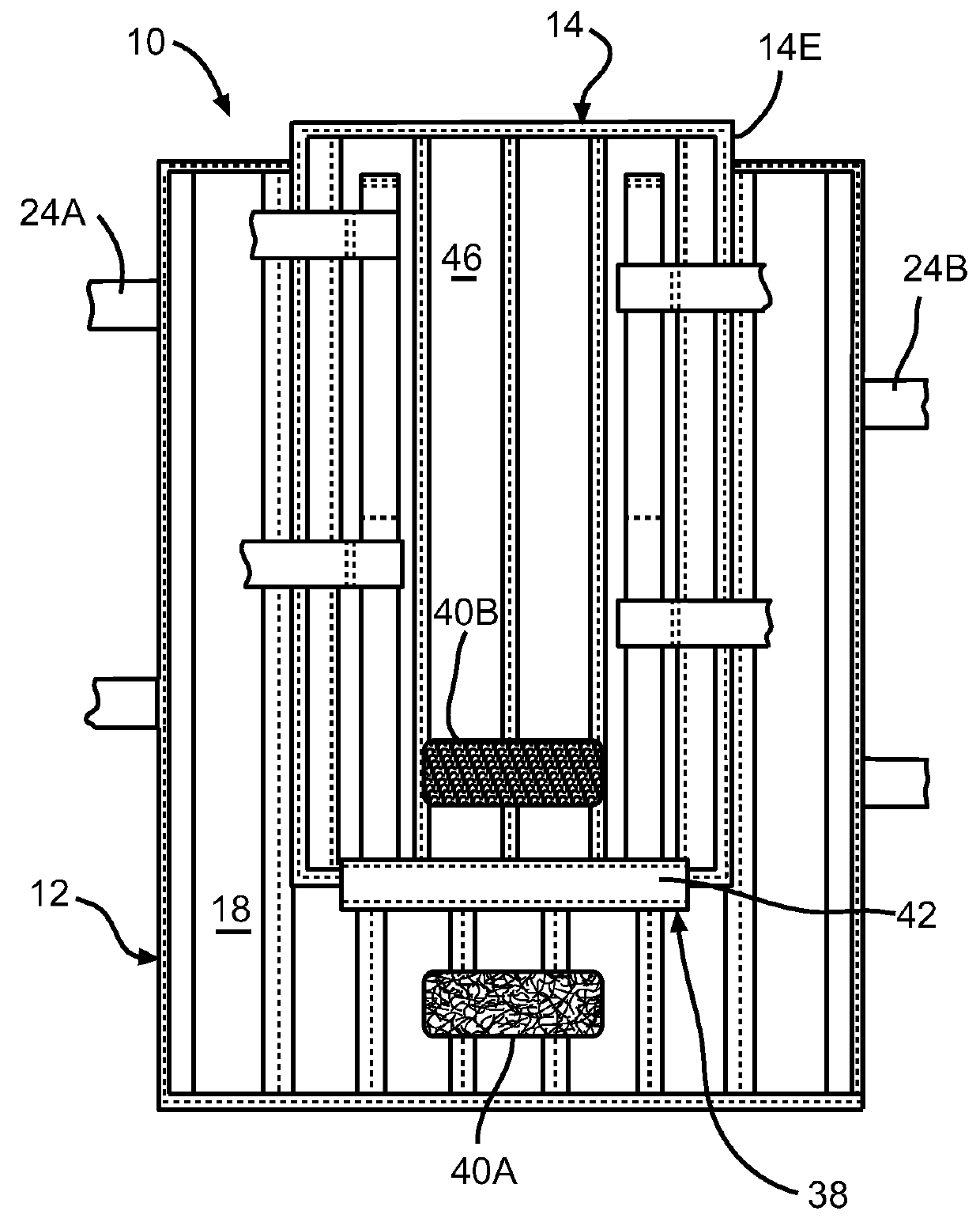
[0040]Referring now to FIG. 3, the splint 10 is shown in a folded or closed position. As best shown in FIG. 3, the second member 14 is attached to the inner surface 18 of the first member 12 by a strip of fabric 38. The strip of fabric 18 may be attached to the inner surface 18 by any suitable means, such as by sewing, mechanical fasteners, or with adhesive. Alternatively, the strip of fabric 38 is not required and the second member 14 may be directly attached to the inner surface 18 of the first member 12 at a seam defined by any suitable means, such as by sewing, mechanical fasteners, or with adhesive. For example, the second member 14 may be attached to the outer surface 16 of the first member 12 at a sewn seam 48 as shown in the splint 110 in FIG. 6.

[0041]If desired, complementary portions 40A and 40B of a fastener, such as a hook and loop fastener may be attached to the inner surface 18 of the first member 12 and the outer surface 46 of the second member 14, respectively. The s...


PUM


Abstract

A splint includes a first substantially flexible member having an inner surface and an outer surface. A second substantially flexible member has an inner surface and an outer surface, and is hingedly attached to the first substantially flexible member. An attachment strap is slidably attached to the outer surface of the first or the second substantially flexible member, and is configured for longitudinal movement relative to the first and second substantially flexible members. A substantially rigid slat is removably mounted relative to at least one of the first and second substantially flexible members.

Description

BACKGROUND OF THE INVENTION[0001]This invention relates in general to splints. In particular, this invention relates to an improved structure for an orthopedic splint for use in the field by military personnel, emergency medical first-responders, athletic trainers, and the like.[0002]Many splinting devices are available for use by military personnel, athletic trainers, emergency medical first-responders and the like to splint, immobilize, and / or stabilize various orthopedic injuries.[0003]One known splint is a vacuum splint, such as described at: http: / / www.ambulancemodification.com / splints.html (accessed Sep. 28, 2012). The vacuum splint includes fabric filled with small foam beads. When air is pumped out of the splint, it retains rigidity. To use the vacuum splint, the fabric is wrapped around the injured limb, and air is pumped out of the splint. The vacuum splint comes in several sizes, each designed for a specific limb. Multiple splints may need to be carried to treat different...

Claims


Application Information

Patent Timeline
Patent Type & Authority Patents(United States)
IPC IPC(8): A61F5/58A61F5/01A61F5/05A61F5/058
CPCA61F5/0102A61F5/058A61F5/01A61F5/05825A61F5/05A61F5/05841A61F5/0104
Inventor AMODT, ZACHARY, T.
Owner AMODT ZACHARY T
Why Eureka
Try Eureka