Image forming apparatus with adjusting belt unit

a technology of image forming apparatus and adjusting belt, which is applied in the direction of electrographic process apparatus, instruments, optics, etc., can solve the problems of high precision, force which acts in the direction of causing the endless belt to laterally shift cannot be ignored without having a negative effect, and the three methods described above cannot be ignored. , to achieve the effect of reducing the amount of an image forming apparatus

Active Publication Date: 2016-01-19
CANON KK
View PDF27 Cites 0 Cited by
  • Summary
  • Abstract
  • Description
  • Claims
  • Application Information

AI Technical Summary

Benefits of technology

[0012]According to the present invention, among the multiple rollers by which an endless belt is supported, the rollers (at least belt driving roller) which are greater in the angle of contact (wrapping angle) between themselves and belt are supported by the rails attached to the main assembly of an image forming apparatus so that they are precisely positioned relative to each other by the rails. Thus, the belt supporting rollers, which have significant effect upon the lateral shifting of the endless belt are kept properly and firmly positioned relative to the main assembly of an image forming apparatus. Therefore, the present invention can prevent the problem that because of the distortion of the intermediary transfer belt unit frame, a belt driving roller becomes misaligned. Therefore, it can substantially reduce an image forming apparatus in the amount of the force which acts in the direction to cause the endless belt to laterally shift.

Problems solved by technology

However, the three methods described above have the following problems.
Further, in the case of the method such as the method (2) which strictly controls the process of manufacturing the belt supporting rollers, in terms of the preciseness of each roller, and regulating the lateral movement of the endless belt, by providing the endless belt with a rib or ribs, the following problems sometimes occurred.
That is, the force which acts in the direction to cause the endless belt to laterally shift cannot be ignored without having a negative effect.
Further, the high level of precision of which the process of manufacturing the endless belt driving system is required increases in cost the components of the endless belt supporting system.
As the belt creeps onto the rib regulating member, it is possible for the endless belt and / or its rib (ribs) to become damaged.
Thus, even if the endless belt supporting device is adjusted after it is installed in the main assembly of an image forming apparatus, for example, the endless belt begins to laterally shift because of the frictional wear of the rollers, changes in the amount of friction between the endless belt and rollers attributable to the surface deterioration of the belt and rollers, stretching of the belt, and / or the like causes.
Consequently, the rib creeps onto the rib regulating member, which will result in damage to the rib itself and / or the belt.
The art disclosed in Japanese Laid-open Patent Application 2005-92153, however, is possibly problematic in that as the transferring means frame, by which the belt supporting rollers are supported, progressively distorts, the rollers become progressively misaligned among themselves.
Eventually, the misalignment becomes too much to be dealt with.
Further, in the case of an image forming apparatus, the belt cleaning member of which is positioned in such a manner that it is pressed against the belt driving roller (belt steering roller), with the presence of the belt between the belt cleaning member and the belt driving roller, the belt cleaning member becomes unstable in the state of contact between itself and the belt, as the belt driving roller is tilted to steer the endless belt.

Method used


Image

  • Image forming apparatus with adjusting belt unit
  • Image forming apparatus with adjusting belt unit
  • Image forming apparatus with adjusting belt unit

Examples


Embodiment Construction

[0024]Hereinafter, one of the preferred embodiments of the present invention is described with reference to the appended drawings. The dimension, material, and shape of the structural components of the image forming apparatus in this embodiment, and the positional relationship among the structural components, are not intended to limit the present invention in scope, unless specifically noted. Further, if two or more components in the appended drawings are the same in referential code, they are the same in structure and / or function. Therefore, if one of them is described, the others are not described.

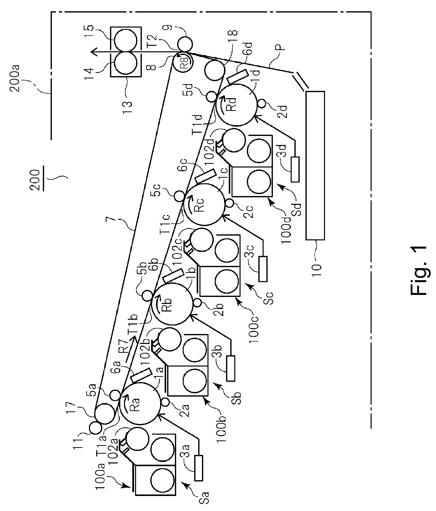
[0025]FIG. 1 is a schematic sectional view of the image forming apparatus in this embodiment of the present invention, and shows the general structure of the apparatus. Referring to FIG. 1, an image forming apparatus 200 is an example of a full-color image forming apparatus (which has copying function, printing function, and facsimile function). The image forming apparatus 200 has a main...


PUM


Abstract

An image forming apparatus assembly includes a main body, and a belt unit mounted to the main body and including an endless belt, a plurality of rollers including a first roller configured to apply a driving force to the belt and to stretch the belt, and a second roller around which the belt is wound with a wrapping angle not less than 90° and configured to stretch the belt, a frame configured to integrally support the rollers, a first engaging portion disposed in the frame and configured to position the first roller to the main body, and a second engaging portion disposed in the frame and configured to position the second roller to the main body. In addition, a guide member is configured to guide the belt unit and disposed in the main body, and including a first engaged portion engaged with the first engaging portion and a second engaged portion engaged with the second engaging portion.

Description

FIELD OF THE INVENTION AND RELATED ART[0001]There are various types of image forming apparatuses which use an electrophotographic image forming method, an electrostatic recording method, or the like, to form an image. Some of them are widely in use as a printer, or a copying machine. They use a photosensitive drum (or photosensitive drums) as their image bearing member(s). They are also provided with such processing means as a charging means, an exposing means, and a developing means, which are disposed in the adjacencies of the peripheral surface of the photosensitive drum. Further, they are provided with an image transfer mechanism, a recording medium conveyance mechanism, an image fixing mechanism, etc.[0002]Further, some of them employ an intermediary transfer member for transferring a toner image on a photosensitive drum onto recording medium. Among them, some have an endless intermediary transfer belt and / or an endless recording medium conveyance belt. The endless intermediary...

Claims


Application Information

Patent Timeline
Patent Type & Authority Patents(United States)
IPC IPC(8): G03G15/01G03G15/16
CPCG03G15/1615G03G2215/00143G03G2215/00156G03G2215/0132
Inventor HATANO, FUKASHI
Owner CANON KK
Why Eureka
Try Eureka