Image forming apparatus

a technology forming apparatus, which is applied in the direction of electrographic process apparatus, instruments, optics, etc., can solve the problems of reducing the productivity increasing the size and/or cost of image forming apparatus, and not allowing the image forming apparatus to form an image, etc., to achieve cost reduction, size reduction, and size increase

Active Publication Date: 2020-06-02
CANON KK
View PDF10 Cites 0 Cited by
  • Summary
  • Abstract
  • Description
  • Claims
  • Application Information

AI Technical Summary

Benefits of technology

[0005]The structural arrangement for placing a cleaning member in contact with the secondary transfer roller as disclosed in Japanese Laid-open Patent Application No. 2007-334011 is likely to increase an image forming apparatus in size and / or cost. In comparison, the structural arrangement for applying a preset bias to a secondary transfer roller is advantageous in terms of cost reduction and / or size reduction. This structural arrangement, however, does not allow an image forming apparatus to form an image during a cleaning period. Therefore, if a cleaning operation is carried out more often than necessary, an image forming apparatus is substantially reduced in productivity.
[0007]Therefore, the primary object of the present invention is to provide an image forming apparatus which does not carry out the operation for cleaning its transferring member for an unnecessarily length of time, and therefore, is not significantly reduced in productivity by the operation for cleaning its transferring member.

Problems solved by technology

The structural arrangement for placing a cleaning member in contact with the secondary transfer roller as disclosed in Japanese Laid-open Patent Application No. 2007-334011 is likely to increase an image forming apparatus in size and / or cost.
This structural arrangement, however, does not allow an image forming apparatus to form an image during a cleaning period.
Therefore, if a cleaning operation is carried out more often than necessary, an image forming apparatus is substantially reduced in productivity.

Method used


Image

  • Image forming apparatus
  • Image forming apparatus
  • Image forming apparatus

Examples


embodiment 1

[Embodiment 1]

1. Overall Structure and Operation of Image Forming Apparatus

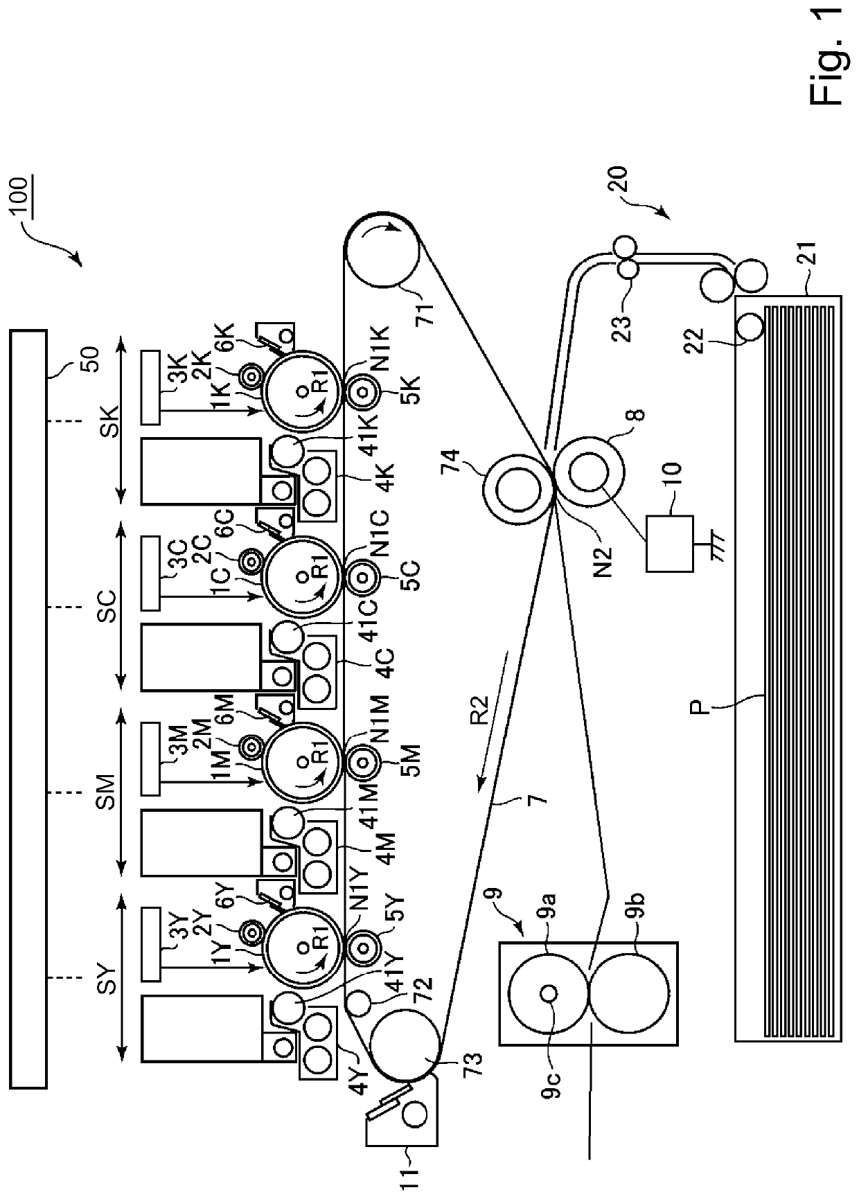
[0027]FIG. 1 is a schematic sectional view of the image forming apparatus 100 in this embodiment. The image forming apparatus 100 in this embodiment is such an image forming apparatus that can form a full-color image with the use of an electrophotographic image forming method. It is of the so-called tandem type, and employs an intermediary transferring method.

[0028]The image forming apparatus 100 has multiple image forming portions (stations), more specifically, the first, second, third and fourth image forming portions SY, SM, SC and SK, which form yellow (Y), magenta (M), cyan (C) and black (K) toner images, respectively. The four image forming portions SY, SM, SC and SK are practically the same in structure and function, although they are different in the color of the toner image they form. Thus, the suffixes Y, M, C and K, which indicate the color of the image they form, may be sometimes omitted to descri...

embodiment 2

[Embodiment 2]

[0060]Next, another embodiment of the present invention is described. The image forming apparatus in this embodiment is the same as the image forming apparatus in the first embodiment, in basic structure and operation. Therefore, the elements of the image forming apparatus in this embodiment, which are the same as, or equivalent to, the counterparts of the image forming apparatus in the first embodiment, in function or structure, are given the same referential codes as those given to the counterparts, one for one, and are not described in detail.

[0061]Also in this embodiment, the length of time the cleaning operation for cleaning the secondary transfer roller 8 is to be carried out is changed based on the information about the smoothness level of the transfer medium P which is to be used for a printing operation. In this embodiment, however, the control portion 50 detects the level of smoothness of the transfer medium P to be used for a printing operation, with the use...

embodiment 3

[Embodiment 3]

[0067]Next, another embodiment of the present invention is described. The image forming apparatus in this embodiment is the same as the image forming apparatus in the first embodiment, in basic structure and operation. Therefore, the elements of the image forming apparatus in this embodiment, which are the same as, or equivalent to, the counterparts of the image forming apparatus in the first embodiment, in function or structure, are given the same referential codes as those given to the counterparts, one for one, and are not described in detail.

[0068]In this embodiment, the image forming apparatus 100 can form images, with the peripheral velocity of its intermediary transfer belt 7 set to one of two values, more specifically, 250 (mm / sec) and 125 (mm / sec). More concretely, the image forming apparatus 100 is designed so that its control portion 50 is enabled to control the rotational speed of the motor which drives the intermediary transfer belt 7, in order to enable t...


PUM


Abstract

An image forming apparatus includes an image transfer belt; a first transfer member; a second transfer member opposed to the first transfer member with the belt therebetween; an applying device for applying a voltage to at least one of the first and second transfer members; and a controller for controlling the applying device to apply to the at least one transfer member a voltage having the same polarity as a regular polarity of toner and a voltage of the opposite polarity to the first transfer member in a cleaning operation. The controller changes a number of image formations to be carried out from a cleaning operation to a next cleaning operation depending on the kind of the sheet. The number controlled by the controller is different depending on the kind of the sheets in a continuous printing job.

Description

FIELD OF THE INVENTION AND RELATED ART[0001]The present invention relates to an image forming apparatus, such as a copying machine, a printing machine, and a facsimile machine, which uses an electrophotographic image formation method, an electrostatic image recording method, or the like.[0002]An image forming apparatus which uses an electrophotographic image forming method or the like outputs an image by forming a toner image on its image bearing member, and transferring the toner image onto transfer medium such as a sheet of recording paper. Transfer of a toner image onto a transfer medium is done by applying voltage to a transferring member which holds transfer medium by pinching the transfer medium between itself and the image bearing member. As a transferring member, a roller (transfer roller) is frequently used, from the standpoint of stability in the contact between itself and the image bearing member. Further, in order to enable an image forming apparatus such as the one desc...

Claims


Application Information

Patent Timeline
Patent Type & Authority Patents(United States)
IPC IPC(8): G03G15/16G03G15/01G03G15/00
CPCG03G15/5037G03G15/0189G03G15/6591G03G15/1675G03G15/5029G03G15/168G03G2215/1652
Inventor YAMADA, TOSHIYUKI
Owner CANON KK
Why Eureka
Try Eureka