Image forming device

a technology of image forming and forming device, which is applied in printing and other directions, can solve the problems of reducing the size of increasing the cost, and the size of the device housing, and achieve the effect of downsizing the image forming devi

Inactive Publication Date: 2015-02-17
RICOH KK
View PDF12 Cites 0 Cited by
  • Summary
  • Abstract
  • Description
  • Claims
  • Application Information

AI Technical Summary

Benefits of technology

[0011]In one aspect, the present invention provides an image forming device including a recording head adapted to discharge liquid drops and a limited number of drive sources which can ensure downsizing of the image forming device.

Problems solved by technology

If plural drive motors are arranged in an image forming device as drive sources for respectively driving plural driven components, such as liquid feed pumps, the suction pumps and the air-vent opening parts, the image forming device will be enlarged in size and the cost will be increased.
However, if an image forming device is provided with a drive transfer device which transfers a driving force of a single drive source selectively to one of the plural driven components described above, then the liquid feed pumps, the suction pumps, the maintenance recovery device, the air-vent opening parts, and the drive transfer device must be arranged in a limited space in the housing of the image forming device.
Consequently, a problem arises that the size of the device housing must be enlarged to accommodate all of such components therein.

Method used


Image

  • Image forming device
  • Image forming device
  • Image forming device

Examples


Embodiment Construction

[0045]A description will be given of embodiments of the invention with reference to the accompanying drawings.

[0046]An embodiment of the image forming device according to the invention will be described with reference to FIGS. 1 to 4.

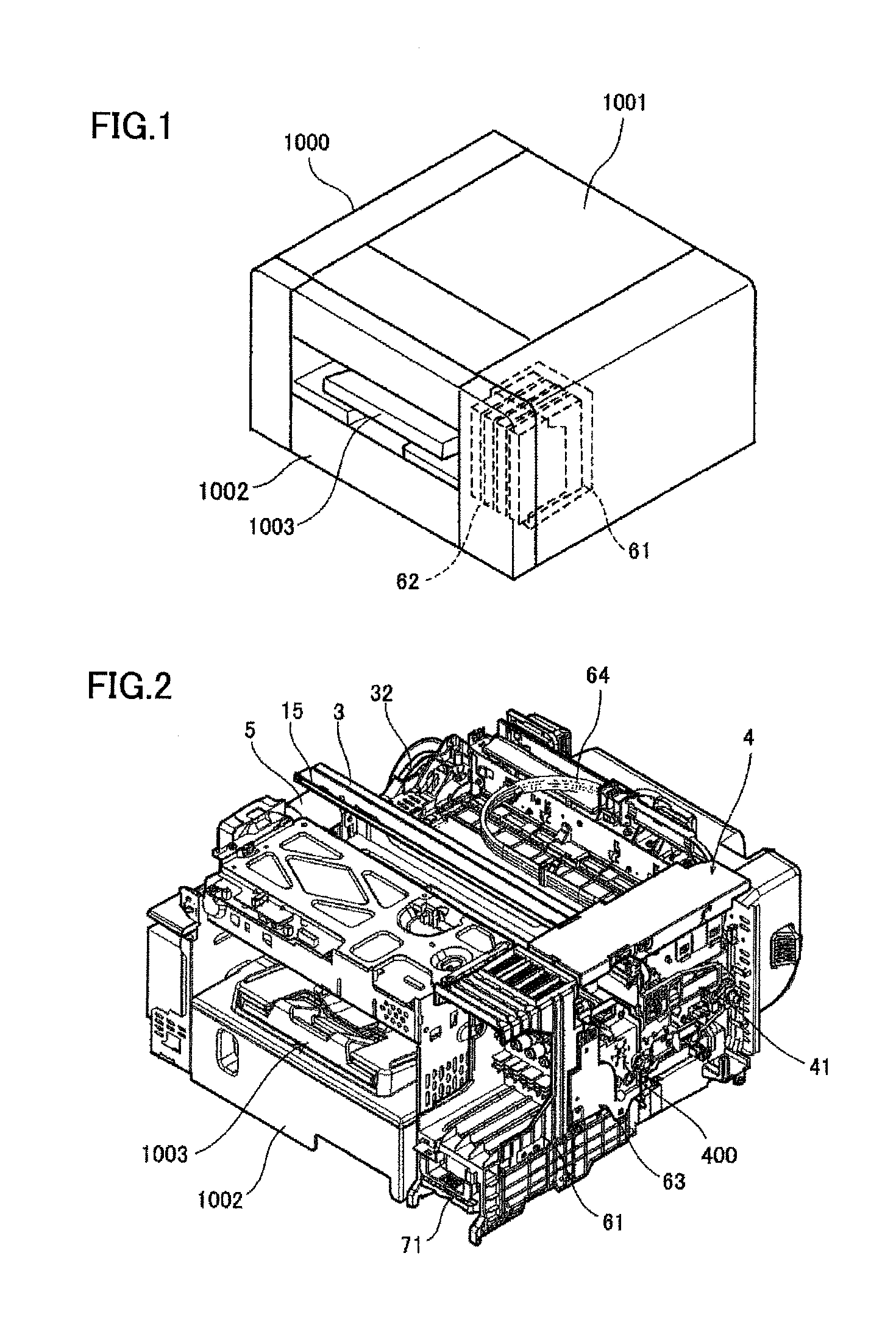
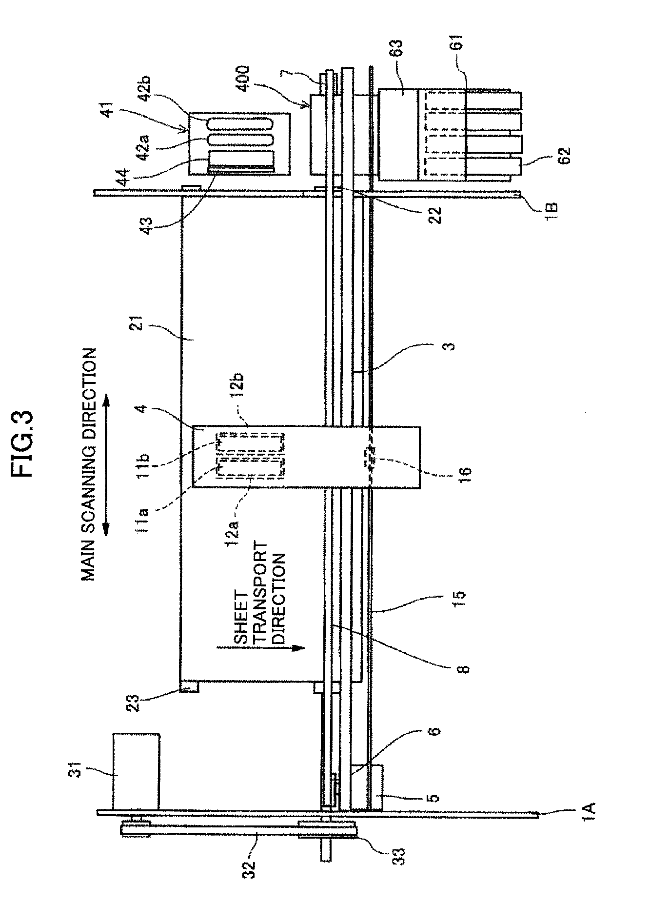
[0047]FIG. 1 is a perspective view showing an appearance of the image forming device according to the embodiment. FIG. 2 is a perspective view of a mechanical part of the image forming device. FIG. 3 is a plan view showing a main portion of the mechanical part of the image forming device. FIG. 4 is a side view showing a carriage portion of the mechanical part of the image forming device.

[0048]The image forming device of this embodiment is a serial type image forming device. A cover 1001 is arranged on a top surface of a housing 1000 so that the cover 1001 may be freely opened or closed. An internal mechanical part of the image forming device may be accessed when the cover 1001 is opened.

[0049]As shown in FIGS. 2 and 3, in the image forming device, a car...


PUM


Abstract

An image forming device includes a drive transfer device that selectively transmits a driving force of a first drive source to one of liquid feed pumps, a suction part of a maintenance recovery device and an air-vent opening part. The air-vent opening part is arranged to have a maximum driving-force transmission path leading to the drive transfer device among the liquid feed pumps, the suction part and the air-vent opening part. The maintenance recovery device, the drive transfer device and the liquid feed pumps are arranged in order in a sheet transport direction. The suction part of the maintenance recovery device and the drive transfer device are arranged on opposite sides of a cap of the maintenance recovery device in the sheet transport direction.

Description

BACKGROUND OF THE INVENTION[0001]1. Field of the Invention[0002]The present invention relates to an image forming device including a recording head adapted to discharge liquid drops.[0003]2. Description of the Related Art[0004]Among image forming devices, including printers, facsimile machines, copiers, plotters, multi-function peripherals, etc., an ink-jet image forming device using a recording head which includes a plurality of liquid drop discharge heads (or liquid discharge heads) to discharge liquid drops is known.[0005]For example, in the ink-jet image forming device of this type, a plurality of main tanks (ink cartridges) which respectively contain inks of different colors to be supplied to a recording head adapted to discharge ink drops of the colors may be provided, and a plurality of head tanks which respectively receive the inks of the colors supplied from the main tanks and supply the inks of the colors to the recording head may be provided.[0006]Moreover, the ink-jet im...

Claims


Application Information

Patent Timeline
Patent Type & Authority Patents(United States)
IPC IPC(8): B41J2/165
CPCB41J2/16505B41J2/16523
Inventor MIWA, ATSUSHISAWAI, TOMOHIROKUBO, ISAMU
Owner RICOH KK
Why Eureka
Try Eureka