Array microphone apparatus for generating a beam forming signal and beam forming method thereof

a microphone and beam forming technology, applied in the direction of transducer circuits, loudspeakers, transducer casings/cabinets/supports, etc., can solve the problems of reducing the application range of end fire techniques, and reducing the quality of voice communication and speech recognition performance, etc., to achieve the effect of suppressing noise in the communication system

Active Publication Date: 2016-02-02
STMICROELECTRONICS SRL
View PDF9 Cites 30 Cited by
  • Summary
  • Abstract
  • Description
  • Claims
  • Application Information

AI Technical Summary

Benefits of technology

[0025]With embodiments described herein, it is possible to obtain an apparatus able to reduce the sound coming, for example, from the directions beside the array microphone (θ=0° and θ=180°) and conversely able to keep the sound coming, for example, from the front of the array microphone (θ=90° and θ=270°).
[0026]Moreover, with embodiments described herein, it is possible to convert an omni-directional microphones array into a bidirectional pattern.

Problems solved by technology

For these applications, the microphones in the system may pick up both the desired voice and also noise.
The noise can degrade the quality of voice communication and speech recognition performance if it is not dealt with in an effective manner able to improve communication quality and voice recognition performance.
However the end fire technique has few applications since deleting front signal sources is generally not suitable for Laptop or Flat panel TV modules.
However, the broad side beam forming technique is generally realized with a complex algorithm performing Fast Fourier Transform (FFT), adaptive suppression, and also inverse FFT.
These techniques appear to be very capable but are not always cost-effective and flexible to use in practical situations.

Method used


Image

  • Array microphone apparatus for generating a beam forming signal and beam forming method thereof
  • Array microphone apparatus for generating a beam forming signal and beam forming method thereof
  • Array microphone apparatus for generating a beam forming signal and beam forming method thereof

Examples


Embodiment Construction

[0039]Although this is not expressly shown, the individual features described with reference to each embodiment shall be intended as auxiliary and / or interchangeable with other features, as described with reference to other embodiments.

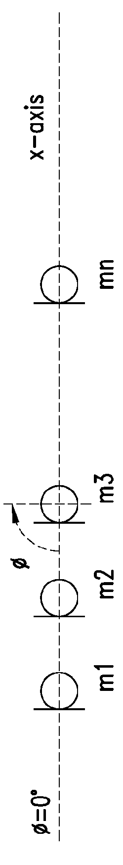
[0040]With reference to FIG. 1, it is indicated with an array microphone apparatus 1 for generating a beam forming signal according to an embodiment.

[0041]The apparatus 1 includes:[0042]at least a first, a second and a third omni-directional microphone, m1, m2 and m3, respectively,[0043]a first directional microphone forming device 2,[0044]a magnitude and phase response handler device 3, and[0045]a combining device 4.

[0046]Each of the omni-directional microphones m1, m2 and m3 are suitable for converting an audible signal into a corresponding first, second and third electrical signal s1, s2 and s3.

[0047]According to an embodiment, one of the omni-directional microphone m1, m2 and m3 is disposed between the other two omni-directional microphones.

[0048]...


PUM


Abstract

Embodiments described in the present disclosure relate to an array microphone apparatus for generating a beam forming signal. The apparatus includes first, second, and third omni-directional microphones, each converting an audible signal into a corresponding electrical signal. The three microphones are arranged in a horizontal coplanar alignment, and the second microphone is disposed between the other two microphones. The apparatus includes a first directional microphone forming device to jointly output a first directional microphone signal with a first bi-directional pattern, and a magnitude and phase response handler device to output a second directional microphone signal with an omni-directional pattern shifted by a prefixed value with respect to first directional microphone signal. The apparatus further includes a combining device receiving the first and second directional microphone signals and outputting a combined directional microphone signal with a combined beam pattern correlated to the first bi-directional and second omni-directional patterns, the combined directional microphone signal being perpendicular to the horizontal coplanar alignment of the first, second, and third omn-directional microphones.

Description

BACKGROUND[0001]1. Technical Field[0002]The present disclosure relates to an array microphone apparatus and in particular to an array microphone apparatus for generating a beam forming signal and a beam forming method thereof.[0003]2. Description of the Related Art[0004]For ease of understanding, the following is a glossary of certain terms used herein:[0005]First order difference pattern: a pattern that is formed as the difference in pressure between two points in space. The two-port microphones often used in hearing aids are of this type.[0006]Cardioid: a first order difference pattern that has maximum response in the forward direction and a single null to the rear.[0007]Bidirectional: general name for any pattern that has equal maximum response in both the front and rear directions.[0008]Many communication system and voice recognition devices are designed for use in noisy environments. Examples of such applications include communication and / or voice recognition in cars or mobile ...

Claims


Application Information

Patent Timeline
Patent Type & Authority Patents(United States)
IPC IPC(8): H04R3/00
CPCH04R3/005H04R2201/403H04R2430/25
Inventor MORCELLI, ALESSANDROVENERI, MARCO
Owner STMICROELECTRONICS SRL
Why Eureka
Try Eureka