Hand-tool brace

a handtool and wristband technology, applied in the field of handtool braces, can solve the problems of hand and wrist discomfort, and fatigue of operators, and achieve the effects of reducing the risk of injury, and improving the safety of hand and wris

Active Publication Date: 2016-02-23
THE BOEING CO
View PDF26 Cites 3 Cited by
  • Summary
  • Abstract
  • Description
  • Claims
  • Application Information

AI Technical Summary

Benefits of technology

[0007]Accordingly, a device for transferring the pressure and vibration of a hand-operated power tool from the wrist to the forearm of the operator may find utility.

Problems solved by technology

It is generally known that prolonged usage of power tools may cause discomfort and fatigue.
More specifically, pressure and vibration from power tools may lead to discomfort in the operator's hands and wrist.
However, the pressure caused by exerting a force on the power tool still results in discomfort to the hand and wrist.
An additional disadvantage of cushioned gloves is that their use reduces grip strength.
A disadvantage of tool balancers is that they cannot be used in certain situations.
Another disadvantage of tool balancers is that they are expensive to install and are not readily available to all operators.
However, ergonomic tools do not necessarily provide a useful advantage to all users.
Hand sizes vary and an ergonomic tool may become uncomfortable if the physical characteristics of a particular operator are not within the design range of the ergonomic tool.

Method used


Image

  • Hand-tool brace
  • Hand-tool brace
  • Hand-tool brace

Examples


example i

Device Example I

FIGS. 1-4 and 6

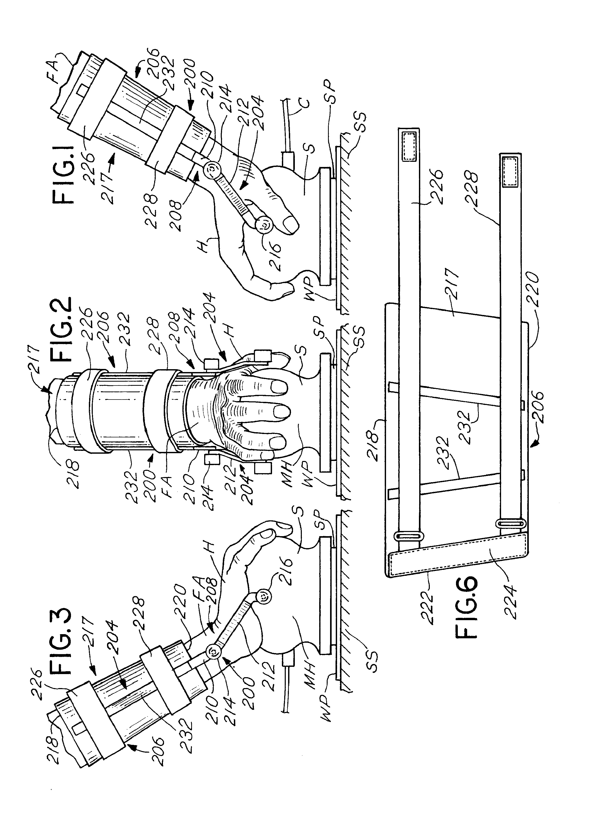
[0036]A device, generally 200, embodied as Device Example I, is illustrated, e.g., in FIGS. 1-3. The device 200 is structured to transfer pressure and vibration of a motorized hand tool, such as a motorized sander S, depicted in FIGS. 1-3, from the hand and wrist to the forearm of the user. The sander S is a type that is operated by downward pressure from the hand H of a human operator. As shown in FIGS. 1-3, the motorized sander S includes a motor housing MH, having an electric power cord C or an air connector operating the motor within the motor housing MH. Sandpaper SP of a type used with the sander S is attached to the movable base of the sander, operated by the motor. During operation of the sander S, such as a rotary sander, the sandpaper SP is sanding a workpiece WP resting on a support surface SS. Although a motorized sander S is shown and will be described herein, the motorized sander MH is only representative of one type of motorized hand too...

example ii

Device Example II

FIGS. 5, 5A and 6

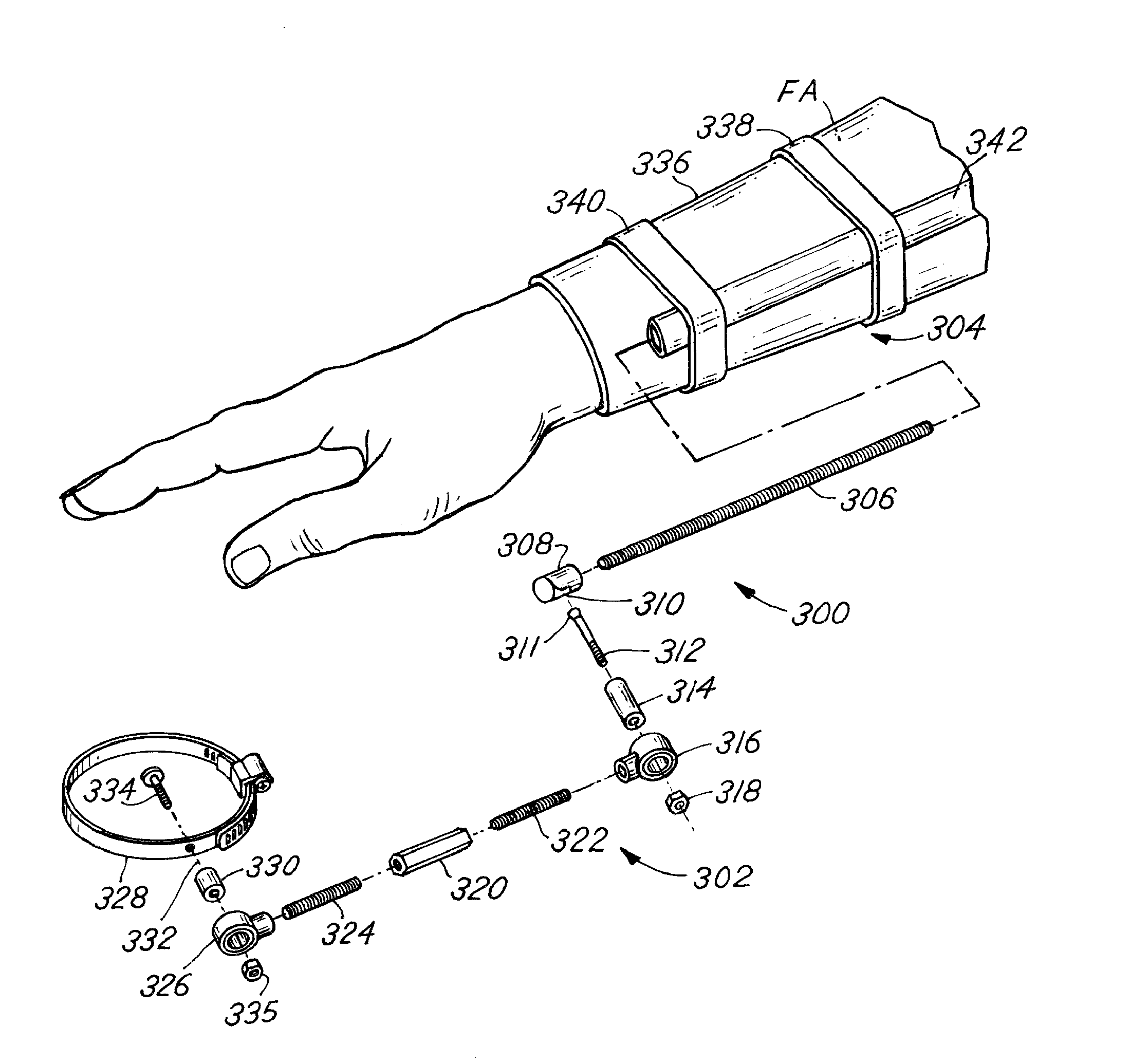
[0046]Referring to FIGS. 5, 5A and 6, a device 300 for transferring pressure and vibration of a motorized hand tool from the hand and wrist of the human operator to the forearm FA of the operator is shown. The device 300 includes a connector, generally 302, that may be coupled to a motorized sander S. For purposes of simplicity, FIGS. 5, 5A, and 6 illustrate only one side of the sander S and one side of a person's hand. It is to be understood that the connector 302 is mounted on both sides of the sander S and on both sides of a person's hand and arm.

[0047]A brace, generally 304, may be coupled or attached to the forearm FA of the human operator. The brace 304 may be coupled to the connector 302. A motorized sander S may be connected to the brace 304, which may be coupled or attached to the right forearm FA of an operator. The motorized sander S has a housing MH, which may include a power cord C, connected to an electrical power source. Sandpaper SP ...

example iii

Device Example III

FIGS. 7 and 6

[0053]A device, generally 400, for transferring pressure and vibration of a motorized hand tool, such as a sander, from the hand and wrist to the forearm FA of an operator is illustrated in FIG. 7. The principal difference in the device 400, as compared to the devices 200 and 300 described above, is the structure of the brace, generally 402. The connector, generally 404, is only partially shown in FIG. 7. The brace 402 generally includes an arm wrap 406 and an overlaying shell 408, which may be rigid or semi-rigid. A lower cinch strap 410 and an upper cinch strap 412 secure the shell 408 to the arm wrap 406 that also protectively covers the forearm FA of the operator.

[0054]The shell 408 includes an upper wall 414 that is sized and shaped to rest on the arm wrap 406 which overlays the surface of the forearm FA of the operator. The shell 408 further includes a connection section comprising a pair of unitary front legs 416 and a pair of unitary rear legs ...


PUM


Abstract

A method and apparatus for transferring vibration of a motorized hand tool from a wrist to a forearm of a human operator is disclosed. The apparatus includes a connector that is coupled to the motorized hand tool and also includes a brace that is coupled to the forearm of the human operator and is also coupled to the connector.

Description

BACKGROUND[0001]Tools, both electrically powered and air powered, such as sanders, drills, saws and the like, are widely used in both industrial and consumer applications. It is generally known that prolonged usage of power tools may cause discomfort and fatigue.[0002]More specifically, pressure and vibration from power tools may lead to discomfort in the operator's hands and wrist.[0003]Cushioned gloves have been used in an attempt to address the above-identified issues. However, the pressure caused by exerting a force on the power tool still results in discomfort to the hand and wrist. An additional disadvantage of cushioned gloves is that their use reduces grip strength.[0004]Tool balancers are helpful in reducing the overall effective tool weight. A disadvantage of tool balancers is that they cannot be used in certain situations. For example, a part being processed may be in a location that is beyond the effective reach of the power tool mounted on a tool balancer. Another disad...

Claims


Application Information

Patent Timeline
Patent Type & Authority Patents(United States)
IPC IPC(8): B25G1/01B25G3/20
CPCB25G1/01B25G3/20Y10T16/502B25F5/006A41D13/015A41D13/08A41D2600/20
Inventor NEALE, ANDREW, LAWRENCE
Owner THE BOEING CO
Why Eureka
Try Eureka