
Walker leg rest

Inactive Publication Date: 2016-03-01
BEMENT DICKIE R
View PDF15 Cites 2 Cited by
  • Summary
  • Abstract
  • Description
  • Claims
  • Application Information

AI Technical Summary

Benefits of technology

[0010]The walker leg rest of this invention is interchangeable for the left or righ

Problems solved by technology

Crutches are undesirable for many reasons.
They are uncomfortable, they require both hands, and they require the user to lift a leg off the ground.
Walkers are not suitable for persons who can use only one leg because considerable upper body strength is required to support the body while suspending one leg.
It is believed that walker leg rests have not achieved commercial success for many reasons.
Some fit only the left or the right leg,

Method used


Image

  • Walker leg rest
  • Walker leg rest
  • Walker leg rest

Examples


Example

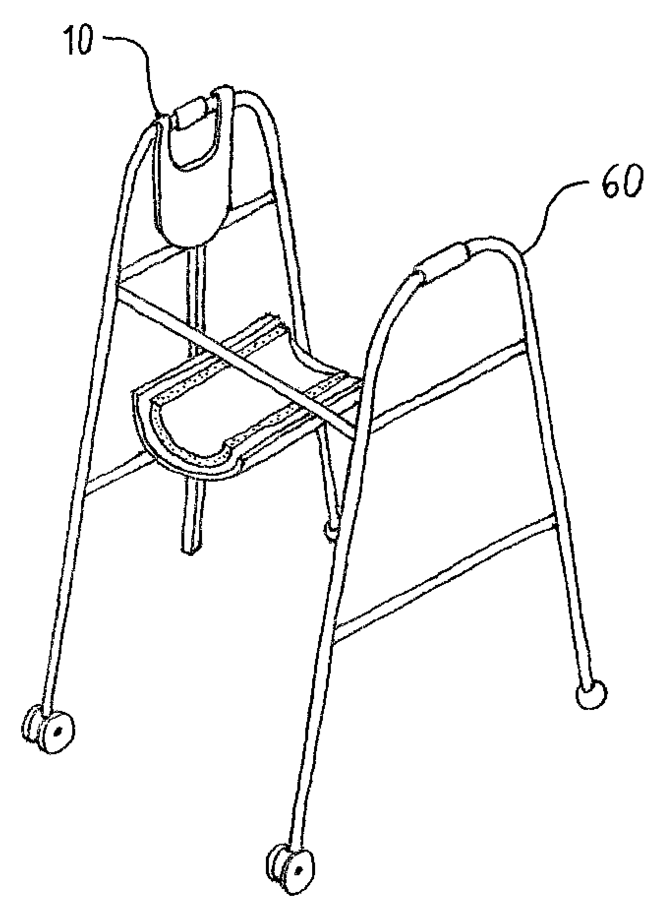
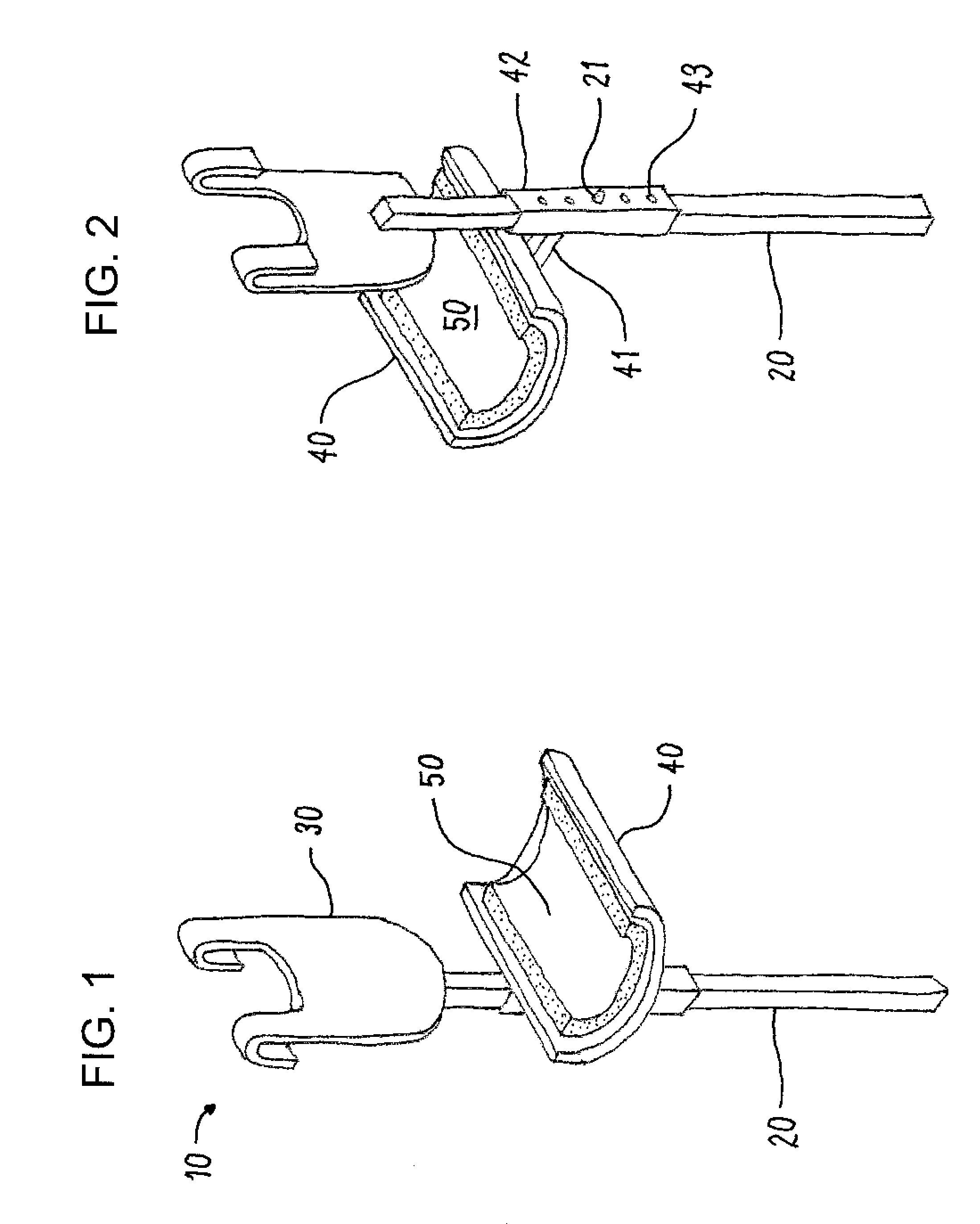
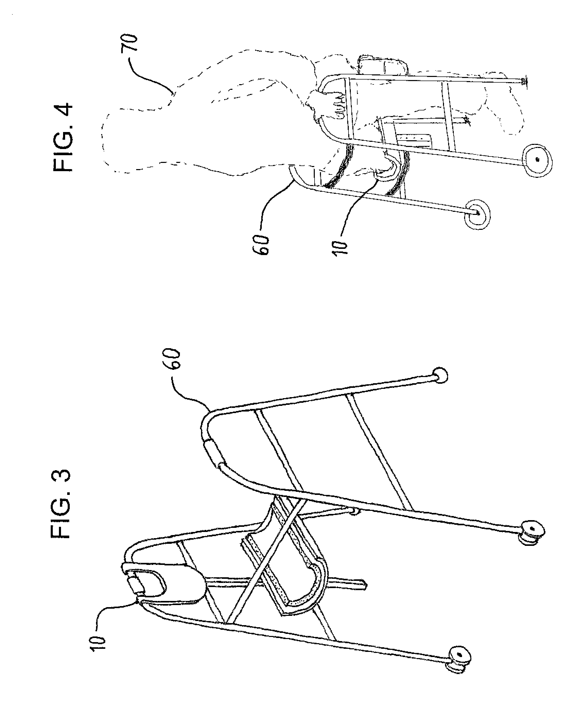
[0015]This invention is best understood by reference to the drawings. Referring first to FIGS. 1 and 2, a preferred embodiment of the walker leg rest 10 of this invention comprises a vertical post 20, a hook 30, a platform 40, and a pad 50. The components are discussed in more detail below.

[0016]The vertical post 20 provides multiple functions. It connects the hook and platform. It rests against one or more of the horizontal bars on the sides of the walker to maintain its vertical orientation when in use. And, in the preferred embodiment, it provides a means for adjusting the height of the platform. The vertical post is preferably hollow to save weight and cost. The vertical post is preferably square in cross-section to provide a flat surface for contact with the horizontal bars and to provide a flat surface for attachment of the hook and the platform. The post is made of a durable material such as metal or molded thermoplastic. Aluminum and steel tend to be more durable, but thermo...


PUM


Abstract

A leg rest for a walker contains: (a) a vertical post having a top; (b) a bifurcated semi-cylindrical hook having a horizontal axis attached to the top of the vertical post, the hook adapted for placement over a handle of a walker; and (c) a leg rest platform attached to one or more of the attachment receptacles of the vertical post.

Description

CROSS-REFERENCE TO RELATED APPLICATION[0001]This application claims the benefit of U.S. Provisional Application Ser. No. 62 / 024,579, Jul. 15, 2014.FIELD OF THE INVENTION[0002]This invention relates to walkers. More particularly, this invention relates to leg rests for walkers.BACKGROUND OF THE INVENTION[0003]A crutch is a mobility device commonly used by persons who cannot use one leg due to injury or disability. The most common type is the underarm crutch, also known as the axilla crutch. An underarm crutch contains a pad that is placed under the armpit. Crutches are undesirable for many reasons. They are uncomfortable, they require both hands, and they require the user to lift a leg off the ground.[0004]A walkers is another type of mobility device. Walkers are commonly used by persons who cannot support all their weight or who cannot balance. Walkers are three-sided frames (front and two sides) with horizontal handles on the sides and with four main legs. The bottoms of the legs c...

Claims


Application Information

Patent Timeline
IPC IPC(8): A61H3/00A45B3/00
CPCA61H3/00A45B3/00A61H2003/005A61H3/04
Inventor BEMENT, DICKIE, R.
Owner BEMENT DICKIE R
Learn More