Treatment device
a treatment device and probe technology, applied in the field of treatment devices, can solve the problems of poorer ability to coagulate or incise biological tissue at the proximal end portion than at the distal end of the prob
- Summary
- Abstract
- Description
- Claims
- Application Information
AI Technical Summary
Benefits of technology
Problems solved by technology
Method used
Image

Examples
first embodiment
[0052][First Embodiment]
[0053]A first embodiment according to the present invention will now be described with reference to the drawings.
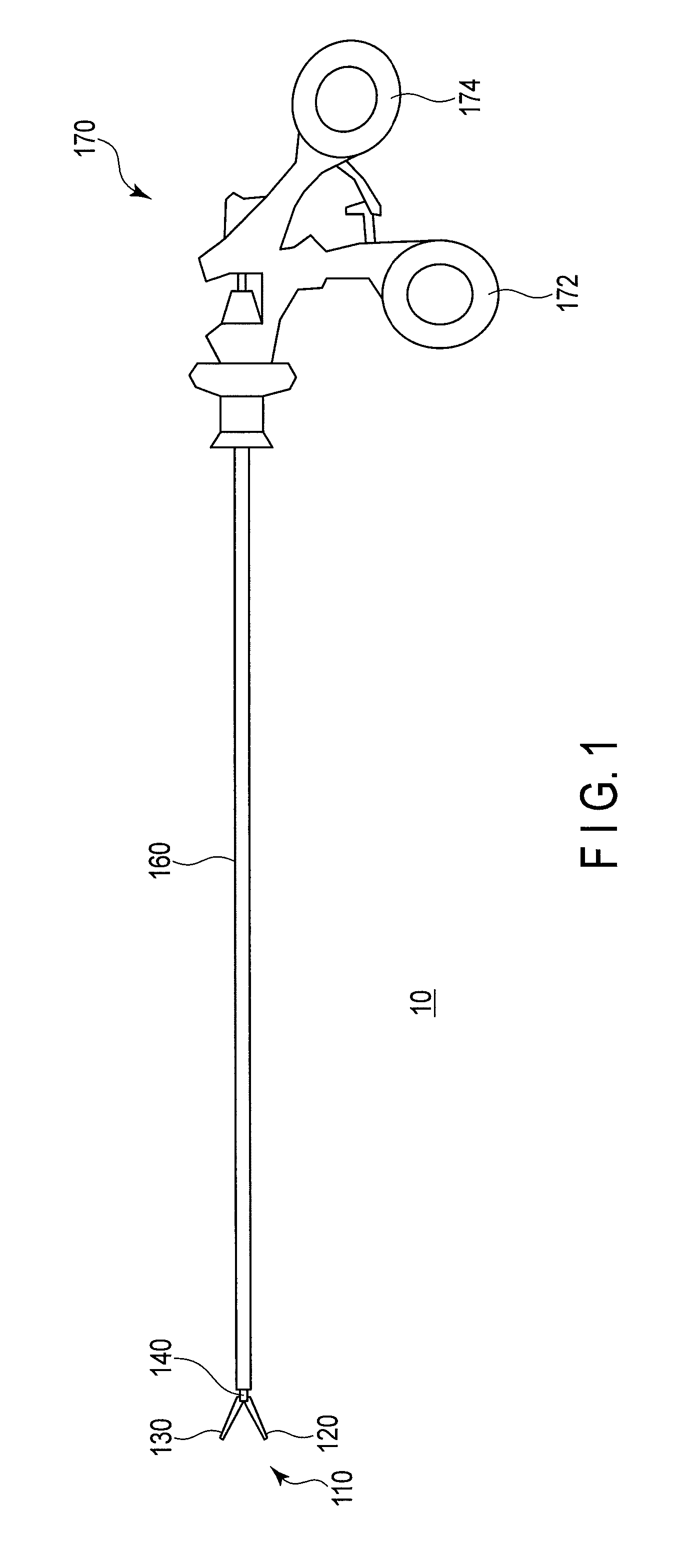
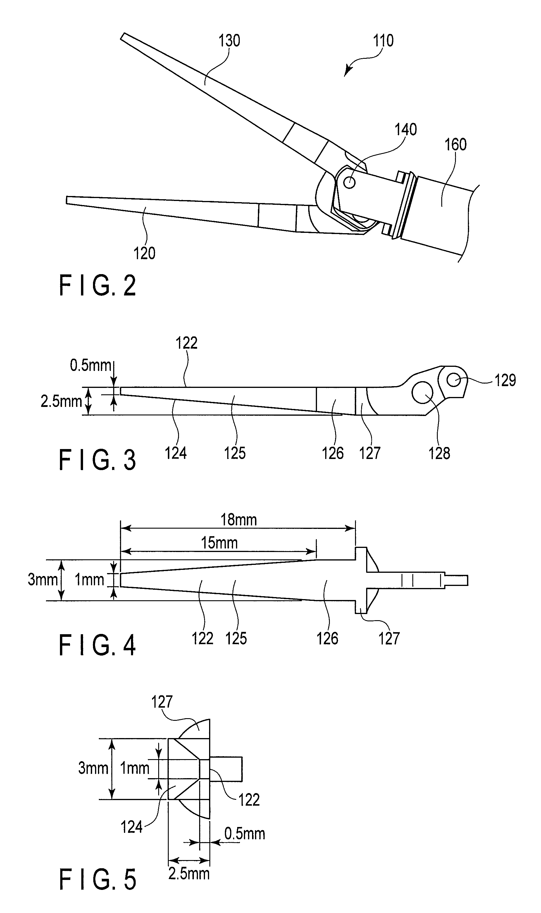
[0054]FIG. 1 shows a schematic view of a pair of forceps 10 according to this embodiment. As shown in this drawing, the forceps 10 includes a distal end portion 110, a shaft 160, and an operating section 170. The distal end portion 110 side will be referred to as a distal end side and the operating section 170 side will be referred to as a proximal end side hereinafter for illustrative purposes.
[0055]FIG. 2 shows a side elevation of the distal end portion 110. As shown in this drawing, the distal end portion 110 includes a first jaw 120 and a second jaw 130. The first jaw 120 and the second jaw 130 turn around a fulcrum pin 140 as an axis and perform an opening and closing operation. The distal end portion 110 grips a biological tissue by using the first jaw 120 and the second jaw 130.
[0056]The forceps 10 is used for, e.g., endoscopic surgery. The ...
second embodiment
[0070][Second Embodiment]
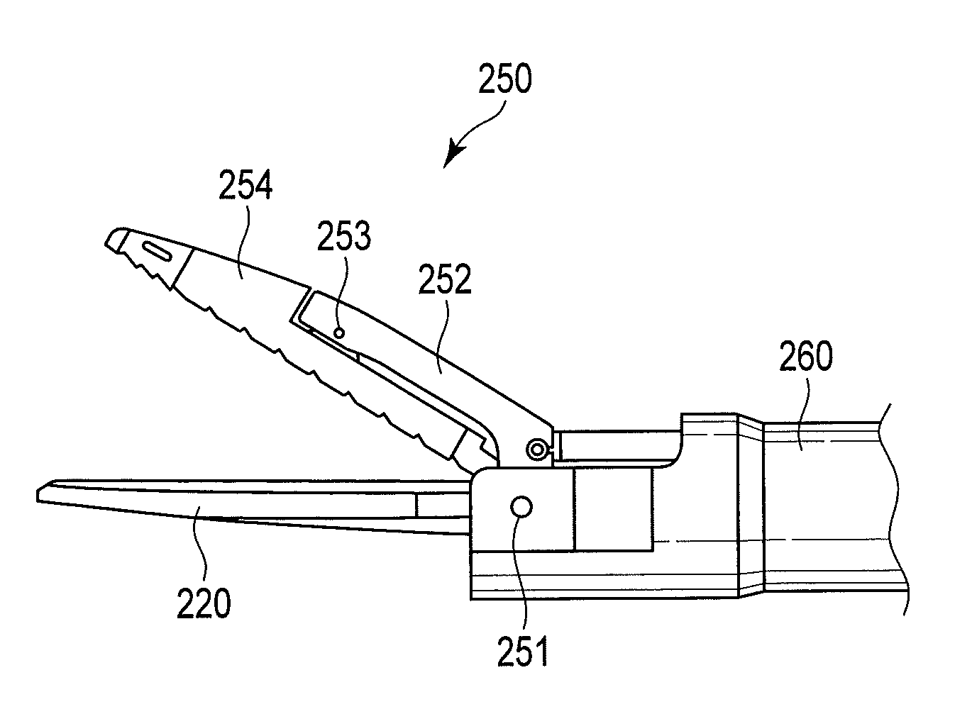
[0071]A second embodiment according to the present invention will now be described. Differences from the first embodiment alone will be explained here, and like reference numerals denote like parts to omit a description thereof. FIG. 9 shows a schematic view of a treatment apparatus 20 according to this embodiment. As shown in this drawing, the treatment apparatus 20 includes a treatment section 210, a shaft 260, an operating section 270, and a power supply unit 290. The distal end portion 210 side will be referred to as a distal end side and the operating section 270 side will be referred to as a proximal end side hereinafter for illustrative purposes. The treatment apparatus 20 grips a biological tissue as a treatment target, e.g., a blood vessel by using the treatment section 210, applies a high-frequency voltage to the gripped biological tissue, and seals or coagulates this biological tissue. Furthermore, the treatment apparatus 20 cuts the biological ti...
third embodiment
[0102][Third Embodiment]
[0103]A third embodiment according to the present invention will now be described. Here, a difference from the second embodiment will be described, and like reference numerals denote like parts to omit a description thereof. In the second embodiment, the ultrasonic vibrator 234 is provided to the operating section 270, and the ultrasonic wave is transmitted to the probe treatment section 220 of the treatment section 210 by the probe 215 inserted in the shaft 260. On the other hand, in this embodiment, an ultrasonic vibrator is provided at a distal end of a shaft 260.
[0104]FIG. 23 shows a structural example of a treatment section 300 provided at the distal end portion of the shaft 260 according to this embodiment. It is to be noted that, in this embodiment, since the ultrasonic vibrator is provided at the distal end portion of the shaft 260, the ultrasonic vibrator is not provided in the operating section 270, and a probe transmitting section 240 that transmit...
PUM
 Abstract
Description
Claims
Application Information
 - R&D
- Intellectual Property
- Life Sciences
- Materials
- Tech Scout
- Unparalleled Data Quality
- Higher Quality Content
- 60% Fewer Hallucinations
Browse by: Latest US Patents, China's latest patents, Technical Efficacy Thesaurus, Application Domain, Technology Topic, Popular Technical Reports.
© 2025 PatSnap. All rights reserved.Legal|Privacy policy|Modern Slavery Act Transparency Statement|Sitemap|About US| Contact US: help@patsnap.com