Eureka AIR delivers breakthrough ideas for toughest innovation challenges, trusted by R&D personnel around the world.

Die having linear bearing array

Active Publication Date: 2016-04-05
ALLIED DIES
View PDF7 Cites 10 Cited by
  • Summary
  • Abstract
  • Description
  • Claims
  • Application Information

AI Technical Summary

Benefits of technology

The invention is a novel die adjusting device for a die apparatus with two die bodies that can bi-directionally and quickly adjust the spacing between the lips of the die bodies. It includes a sliding member connected to a cross-bar, linear moving members, slide fasteners, pivoting members, and a flexible lip that moves about a hinge. The device can easily adjust and control the positioning of the lip, achieving improved die adjusting accuracy.

Problems solved by technology

Applicants have realized that known adjusting devices fail to teach a die adjusting apparatus that provides bi-directional, quick, accurate and repeatable adjusting of the gap between lips of adjacent die bodies.
Prior devices have also been deficient in maintaining a uniform gap that runs the width of the die, especially for dies that are relatively wide.

Method used


Image

  • Die having linear bearing array
  • Die having linear bearing array
  • Die having linear bearing array

Examples


Embodiment Construction

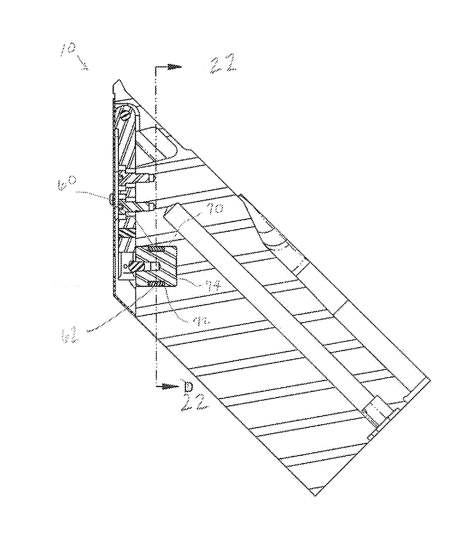
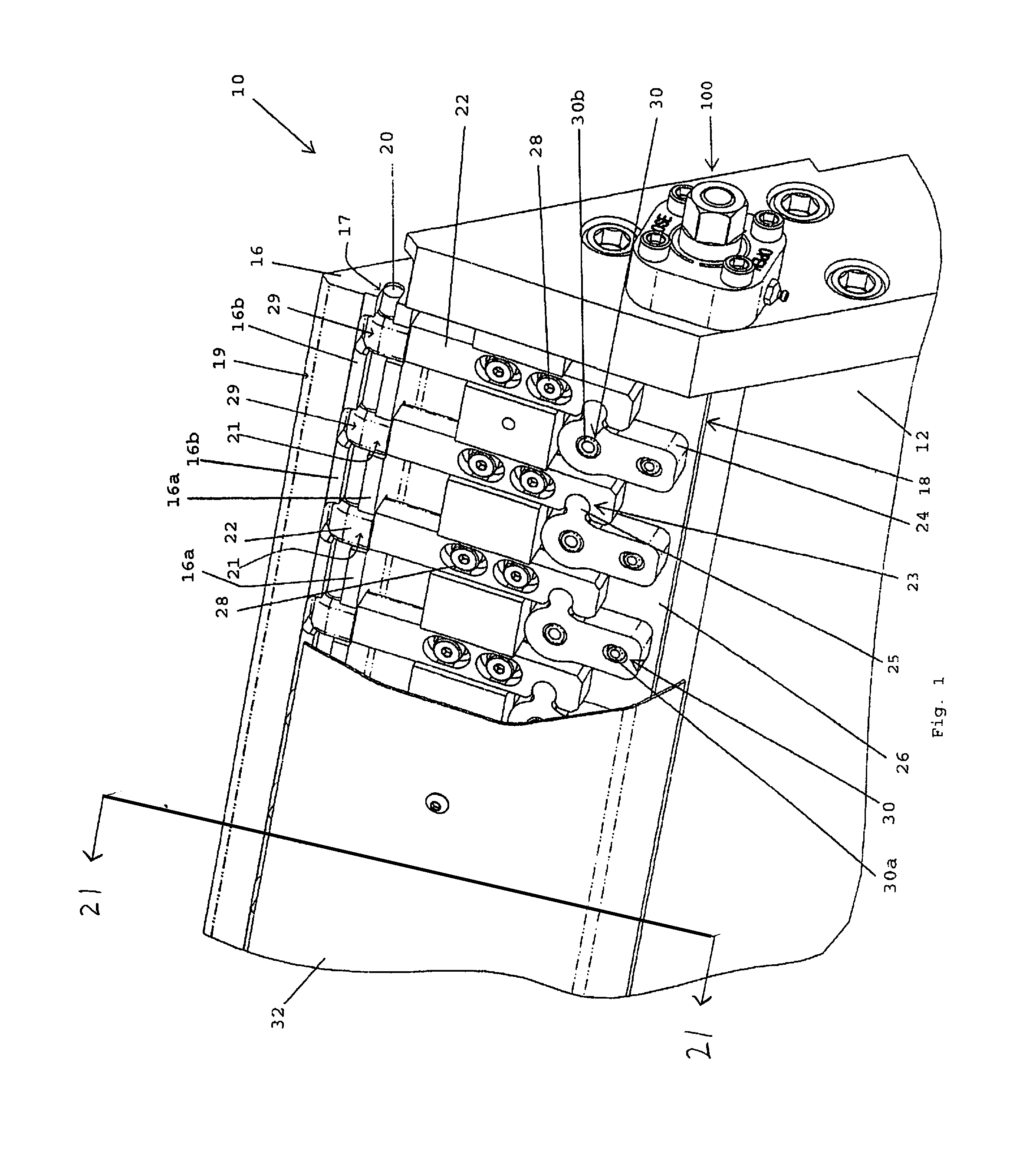
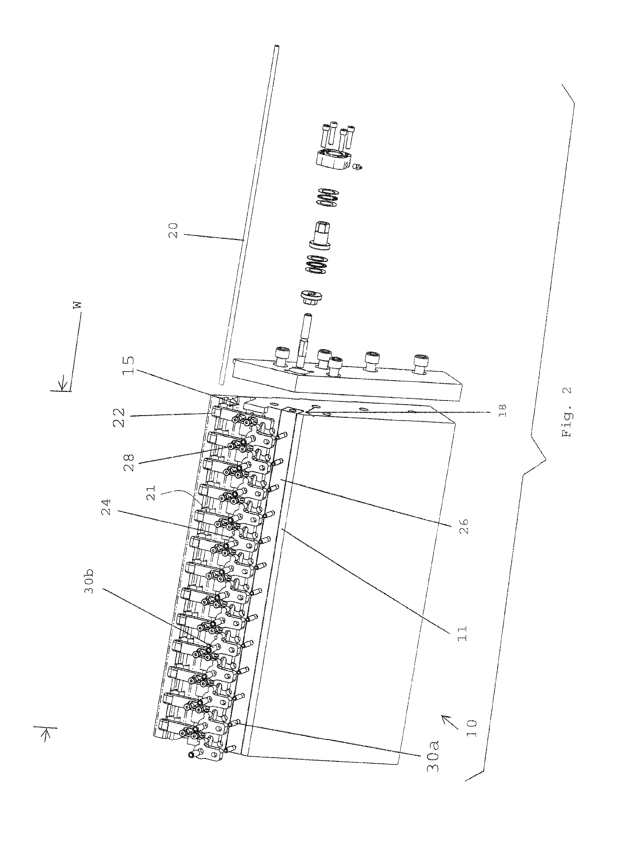
[0051]Referring now to FIGS. 1-25, the invention is directed to a lip adjustment system used in, or with, a die assembly comprising at least two die bodies 10 (depicted in FIGS. 4 and 5 as first die body 10a and second die body 10b for clarity purposes). Portions of the adjustment system may be kept from view by cover 32, as seen in FIG. 1, and may comprise die bodies 10, where at least one of die bodies 10 may have a main body, a hinge 14 and a lip 16. Further, the system may include a cross-bar 20, linear moving members 22, slide fasteners 28, pivoting members 24, pivot fasteners 30 and a sliding member 26 communicating with one another and die body 10. At least one of die bodies 10 (i.e., 10a in FIGS. 4 and 5) may include a flexible lip 16 that may be capable of being spatially moved (e.g., moved toward and away from a paired lip) with respect to a lip of the second die body (i.e., 10b in FIGS. 4 and 5). The above elements of the adjustment system may be connected in such a manne...


PUM

PropertyMeasurementUnit
Lengthaaaaaaaaaa
Flexibilityaaaaaaaaaa
Widthaaaaaaaaaa

Abstract

A die apparatus including a flexible lip integrally connected to a main body, the lip configured to adjust a gap between the flexible lip and a second lip and includes a slide bar equipped with an array of linear bearings where the slide bar and bearings are positioned in a slot of the main body, the slot positioned in a spaced relation from the lip. In one aspect the slide bar includes a threaded hole to receive a fastener configured to fasten a pivot member to the slide bar, the pivot member configured to pivot in order to adjust the lip. The slide bar and bearings may be used on a variety of die apparatus having an integrally connected lip.

Description

[0001]The present application is a continuation-in-part of, and claims priority to, co-pending U.S. patent application Ser. No. 12 / 953,194, filed on Nov. 23, 2010, which is hereby incorporated by reference as if fully reproduced herein.BACKGROUND OF THE INVENTION[0002]1. Field of the Invention[0003]The present invention relates generally to dies for extruding materials, and more specifically to die adjustment devices for adjusting a gap or gaps between adjacent portions of die bodies.[0004]2. Background Information[0005]Flat sheet or film extrusion dies typically include a pair of die bodies that operate to form an outlet through which material is extruded. Each die body may typically include a lip, where the lips may at least partially form the outlet. Further, at least one of the lips may be a flexible lip that is capable of being adjusted to provide a particular sheet or film thickness of the material.[0006]The flexible lips of the prior art extrusion dies may be adjusted and con...

Claims


Application Information

Patent Timeline
IPC IPC(8): B29C47/16B29C47/12B29C47/00B29C48/07B29C48/30B29C48/31
CPCB29C47/122B29C47/165B29C47/16B29C47/0019B29C47/0021B29C48/92B29C48/2566B29C2948/92647B29C2948/92904B29C2948/92942B29C48/313B29C48/07B29C48/08B29C48/301B29C48/31
Inventor DARROW, DOUGLASSCHEMENAUER, JESSE
Owner ALLIED DIES
Why Eureka
Eureka Blog
Learn More