Eureka AIR delivers breakthrough ideas for toughest innovation challenges, trusted by R&D personnel around the world.

Lip adjustment push system

a push system and push plate technology, applied in the field ofdies, can solve the problems of deficient maintenance of the width of the die, known adjusting devices fail to teach single-sided die adjusting devices, prior devices deficient in maintaining uniform gaps, etc., to achieve the effect of swiftly and accurately adjusting the spacing between adjacent parts

Active Publication Date: 2014-04-22
ALLIED DIES
View PDF5 Cites 9 Cited by
  • Summary
  • Abstract
  • Description
  • Claims
  • Application Information

AI Technical Summary

Benefits of technology

The invention is a new die adjusting mechanism for extrusion dies. The mechanism allows for quick and accurate adjustment of the gap between the lips of adjacent die bodies. This mechanism is easy to use, has low manufacturing costs, and requires minimal force to make the lip adjustment. The invention solves the problem of known adjusting devices not being able to provide a single direction, quick, accurate, and repeatable adjustment of the gap between lips of die bodies. The invention also allows for a wide range of lip-gap dimensions in extrusion processes.

Problems solved by technology

Applicants have realized that known adjusting devices fail to teach a die adjusting apparatus that provides single direction, quick, accurate and repeatable adjusting of the gap between lips of adjacent die bodies.
Prior devices have also been deficient in maintaining a uniform gap that runs the width of the die, especially for dies that are relatively wide.

Method used


Image

  • Lip adjustment push system
  • Lip adjustment push system
  • Lip adjustment push system

Examples


Embodiment Construction

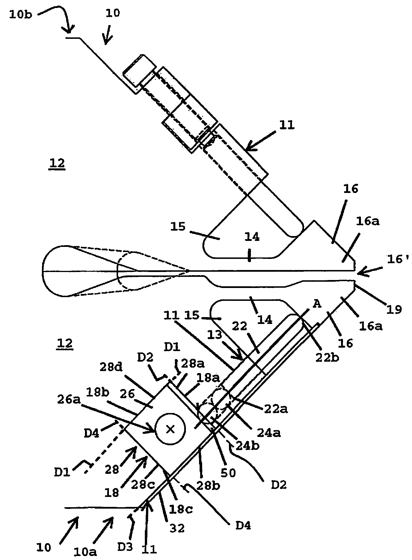
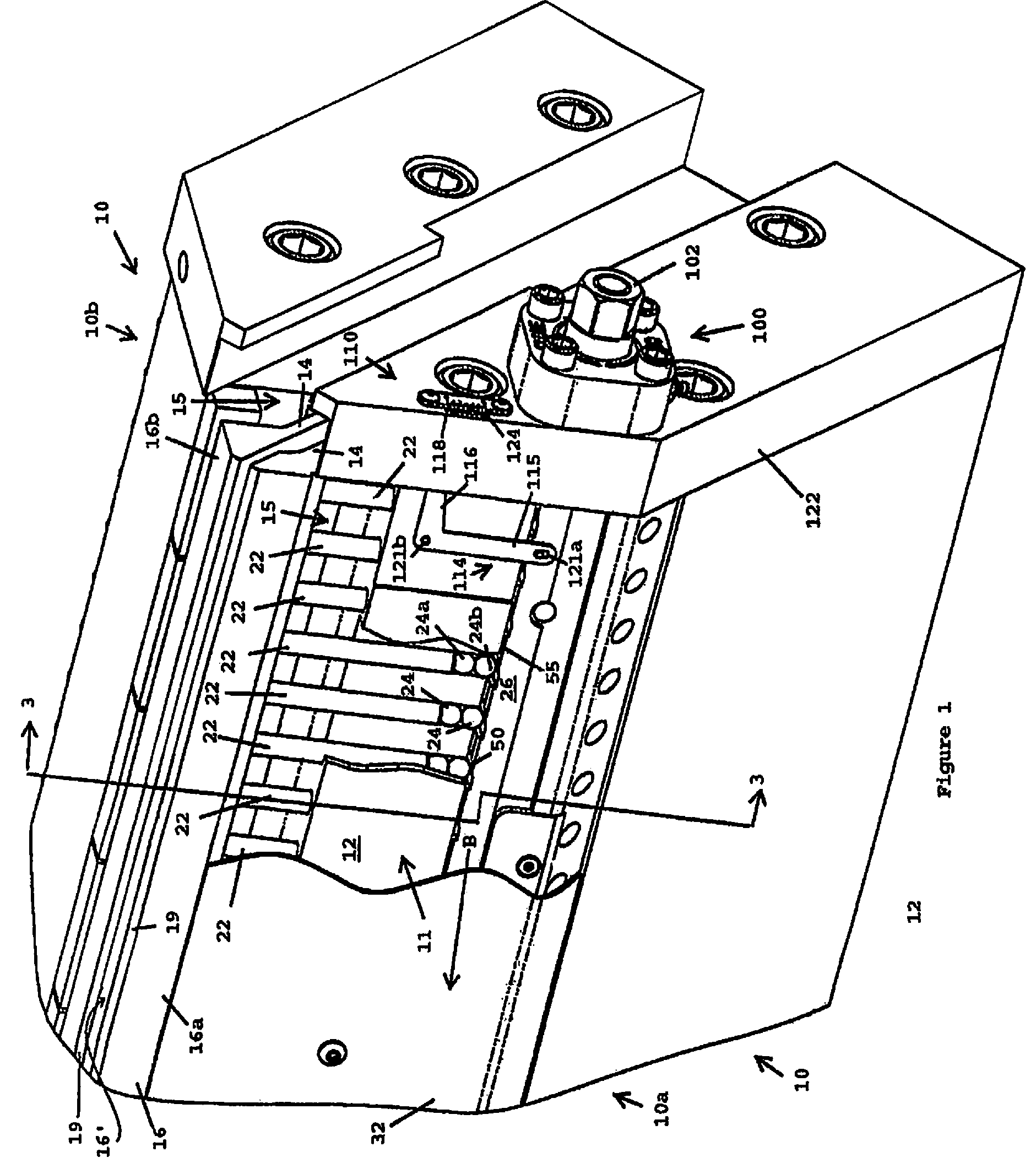
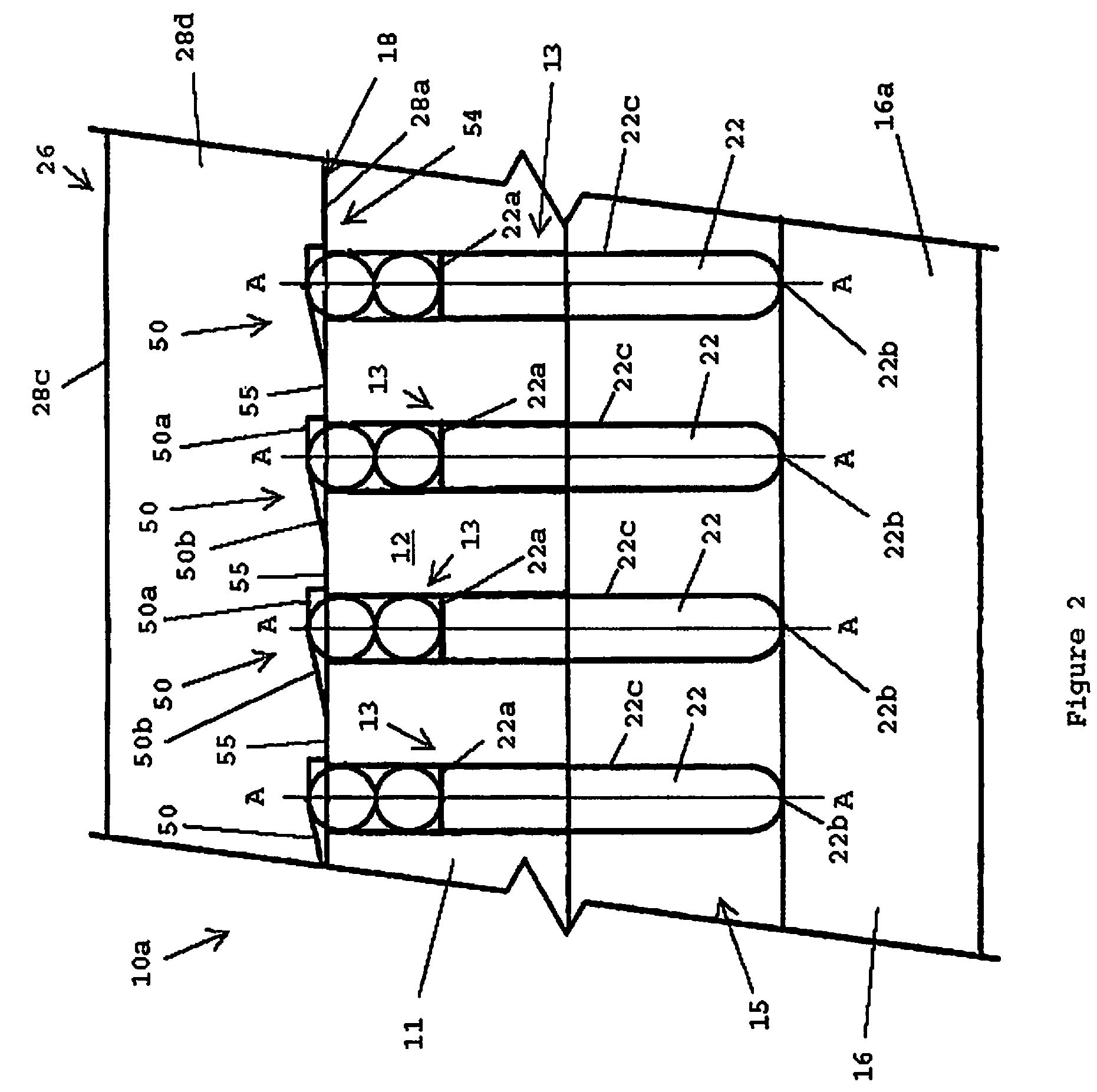
[0026]Referring now to FIGS. 1-6, the invention is directed to a lip adjustment system used in, or with, a die assembly having a lip gap 16′ (depicted in FIG. 1 as gap 16′ between first die body 10a and second die body 10b). When assembled, portions of the adjustment system may be kept from view by cover 32, as seen in FIG. 1, and may comprise die bodies 10, where at least one of die bodies 10 (e.g., one of a first die body 10a and a second die body 10b) may have a main body 12, a hinge 14 and a lip 16. Further, linear moving members 22, optional ball bearings 24, and a sliding member 26 may communicate with one another and the at least one of die bodies 10 to adjust lip gap 16′. The at least one of die bodies 10 (i.e., 10a in FIG. 1) may include a first flexible lip 16a that is capable of being spatially moved with respect to a second flexible lip 16b of the second die body 10b (e.g., lip 16a may be moved toward and away from a paired lip 16b). The above elements of the adjustment ...


PUM

PropertyMeasurementUnit
widthsaaaaaaaaaa
movementaaaaaaaaaa
flexibleaaaaaaaaaa

Abstract

The invention comprises a die apparatus including a flexible lip for adjusting a gap between the flexible lip and a second lip. The apparatus includes linear moving members that are adjusted through operative communication with gradients on a slide bar. Ball bearings may be in operative communication with the gradients of the slide bar. Movement of the slide bar causes the ball bearings to move linearly, which, in turn, cause the linear moving members to move in a similar linear direction. The moving members operatively communicate with the lip. As a result, the dimensions of the gap may be changed by moving the slide bar in a first direction.

Description

BACKGROUND OF THE INVENTION[0001]1. Field of the Invention[0002]The present invention relates generally to dies for extruding materials, and more specifically to die adjustment devices for adjusting a gap or gaps between adjacent portions of die bodies.[0003]2. Background Information[0004]Flat sheet or film extrusion dies typically include a pair of die bodies that operate to form an outlet through which material is extruded. Each die body may typically include a lip, where the lips may at least partially form the outlet. Further, at least one of the lips may be a flexible lip that is capable of being adjusted to provide a particular sheet or film thickness of the material.[0005]The flexible lips of the prior art extrusion dies may be adjusted and controlled by a controlling mechanism, as exemplarily described in U.S. Pat. No. 6,663,375 (“'375”) to Ulcej and U.S. Pat. No. 6,017,207 (“207”) to Druschel. As shown in the '375 and '207 patents, a controlling mechanism may include links ...

Claims


Application Information

Patent Timeline
Patent Type & Authority Patents(United States)
IPC IPC(8): B29C47/16B29C48/31B29C48/08
CPCB29C47/16B29C48/31B29C48/08
Inventor PITSCH, BRIAN M.SCHEMENAUER, JESSE J.
Owner ALLIED DIES
Why Eureka
Eureka Blog
Learn More